Page 6 of 6
Re: Carriage Stop Ring 516667, the intended function??
Posted: Wed Jun 01, 2016 9:49 pm
by robinson46176
dusty wrote: I have gotten back to work on the RV renovation.
I was just wondering a few days ago about that project. I was looking at my old motorhome to make a list of things I need to do to it this month and your project popped into my mind.
Sometimes things do that.

Sometimes we have to shuffle priorities to fit where we are at any given time. Seems to work out.

.
Re: Carriage Stop Ring 516667, the intended function??
Posted: Mon Dec 12, 2016 12:48 pm
by jms
Well let me revive this one - and ask a question.
What if you have a 510 that didn't come with a bumper. Should I buy the newer bumper and just go from there, I assume even if the blade is not in the center of the saw insert cutout it would still make repeatable alignment easier vs no bumper at all - thoughts???
Re: Carriage Stop Ring 516667, the intended function??
Posted: Mon Dec 12, 2016 1:01 pm
by algale
I'd order one. The bumper puts the blade close to the center of the cut out. It's handy when sliding the carriage over to change into saw mode or changing blades to know that if you push the carriage over until it hits the bumper, the table is going to come down where it is supposed to. But it isn't an alignment tool nor is it precise enough to ensure repeat cuts of the same dimensions where accuracy really matters.
Re: Carriage Stop Ring 516667, the intended function??
Posted: Mon Dec 12, 2016 2:10 pm
by wa2crk
The spacer also provides protection from metal to metal contact between the headstock and the table carriage.
Bill V
Re: Carriage Stop Ring 516667, the intended function??
Posted: Mon Dec 12, 2016 3:06 pm
by ecom1
I'm not sure if anyone else mentioned it, but main table alignment will change this. I had one of those defective trunnions with the small hole - before I got the trunnion, my blade was centered in the insert (but not parallel to the table) - after the trunnion was replaced, the blade sat far to the left, so I made a small shim and put in on the way tube to correct the difference.
Makes me think I should make a new "bumper" out or hardwood ply to the thickness needed...
Re: Carriage Stop Ring 516667, the intended function??
Posted: Mon Dec 12, 2016 3:25 pm
by beeg
ecom1 wrote:Makes me think I should make a new "bumper" out or hardwood ply to the thickness needed...
Or a piece of PVC pipe, with a slit in it. So ya can jusr slip it over the way tubes.
Re: Carriage Stop Ring 516667, the intended function??
Posted: Mon Dec 12, 2016 3:28 pm
by ecom1
beeg wrote:Or a piece of PVC pipe, with a slit in it. So ya can jusr slip it over the way tubes.
That works too - even easier!
Re: Carriage Stop Ring 516667, the intended function??
Posted: Mon Dec 12, 2016 6:00 pm
by dusty
ecom1 wrote:beeg wrote:Or a piece of PVC pipe, with a slit in it. So ya can jusr slip it over the way tubes.
That works too - even easier!
Making a new stop ring (or buying one from Shopsmith) does not completely resolve the issue. You must first decide where in the table insert cutout you want the blade to be when you have the "table perfectly aligned". Do you want the left surface of the blade to be on the center line, or do you want the right surface to be on the center line. Or, maybe you want the center line to run right down the "center" of the blade?
There was a time when I said that what was most important was where Shopsmith intended it to be when the rig was designed. I won't say that anymore because Shopsmith will not declare a definitive position on where that should be.
I now position the table so that the center of my 1/8" setup disk from infinity is on that centerline. When I have it there, I secure the trunnion bolts and consider that table alignment complete.
I think that this sketch shows clearly why I think the way I do.
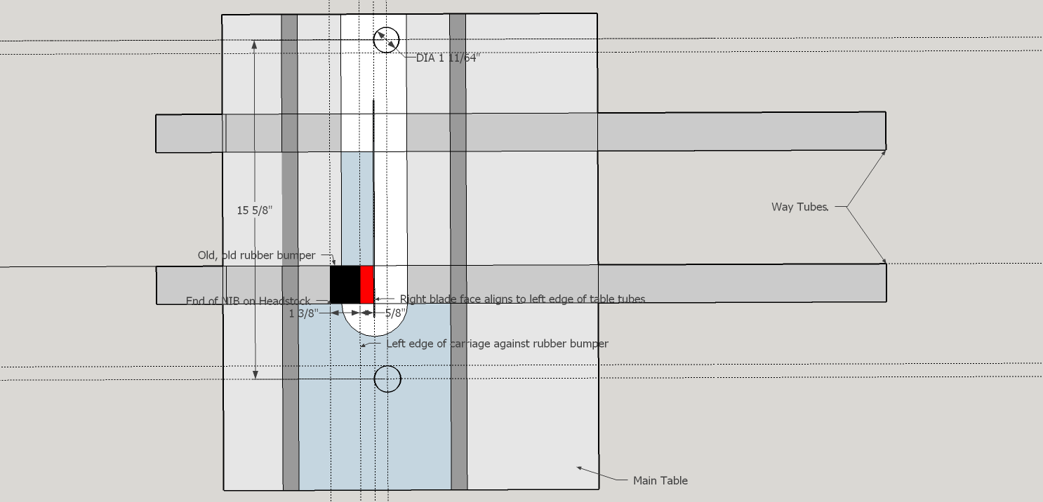
- The Cut Line and the Stop Ring on a 1991 Mark V Model 510.png (37.16 KiB) Viewed 5731 times
I have removed some dimensions from this drawing so as to not imply where that is dimensionally. That is dependent upon a number of key factors.
I loosen the trunnion bolts on the table and insert between the setup disk an either edge of the table cutout, a 1.444" +-.002"spacer. I then move the table to trap that spacer in location and tighten the trunnion bolts. The table is aligned. This means that the miter slots are parallel to the blade and the blade is located in the cutout where I want it.
Setup could not be simpler.
Side Comment: Note where the cutline is with respect to a line drawn between the table uprights (left side). This is center of rotation for the tilting table.