Page 7 of 9
Re: Bandsaw Table Installation and Alignment
Posted: Thu Mar 25, 2021 11:03 am
by edma194
JPG wrote: ↑Thu Mar 25, 2021 10:51 am
Both wheels are 'beveled'. The od of the wheel on the side closest to the base is greater than the od of the wheel at the open side.
The upper portion of the blade laying flat on that bevel on the lower wheel will tilt away from the open side.
Thanks, makes sense.
Re: Bandsaw Table Installation and Alignment
Posted: Thu Mar 25, 2021 1:26 pm
by JPG
Yer making it too complicated. The blade tracks towards the larger od of the wheels. Think about crowned wheels and belts. The lip keeps the blade from slipping off the inner edge. However before the blade reaches the lip, the guide bearings limit the travel to about 1/8" away from the lip. Often overlooked is the lower guide bearing that controls the positioning of the blade as it contacts the lower wheel(just like the obvious one on the upper wheel).
The upper wheel cant merely provides a flat surface for the blade to ride on. Since both wheels are beveled(2°), the blade loop tilts to lie flat on the lower wheel bevel. Since both wheels are beveled the same amount, the upper wheel must be canted(tilted back) to provide a flat surface for the blade. It needs to be twice the bevel angle(4°) [s/b 1.25°]. The cant is not providing the force to push the blade towards the guide bearings. BUT if the cant is insufficient, the blade tends to slip off the outer edge of the upper wheel since the back EDGE of the blade will be the only thing contacting the wheel.
Re: Bandsaw Table Installation and Alignment
Posted: Thu Mar 25, 2021 1:50 pm
by chapmanruss
Ed,
According to the chart your Bandsaw serial number 135408 was made sometime after November 1987 but date codes started in December. Yours would have been the 2945th one made in November when only about 500 were made in the preceding months. This is not the first tool I have seen with a serial number that exceeds when date codes started. The two older Bandsaws are from September 1985 for S/N 113956 and March 1983 for S/N 75210 and all three made by Shopsmith Inc.
JPG said,
I believe the 1984 SS quote is simply inaccurate.
I agree with JPG since this is not the only incorrect information to come directly from Shopsmith. I have received incorrect information from them before on the Bandsaw.
I am trying to understand JPG's statement,
Both wheels are 'beveled'. The od of the wheel on the side closest to the base is greater than the od of the wheel at the open side.
The upper portion of the blade laying flat on that bevel on the lower wheel will tilt away from the open side.
Is the base as referred to in JPG"s post the Main Frame Assembly as it is called in the parts list to which everything attaches to? If so wouldn't the OD of the wheel being larger to the inside and the OD being smaller to the open side cause the blade to move off the front/open side of the wheel? Is that countered by the wheel being tilted on it's axle? Sorry JPG this has me confused. I will have to check this out with my 1956 Bandsaw to try to understand it.
EDIT:
JPG,
You posted your last comments just before I did. I will try to understand it looking at my 1956 Bandsaw.
Re: Bandsaw Table Installation and Alignment
Posted: Thu Mar 25, 2021 9:16 pm
by JPG
JPG wrote: ↑Thu Mar 25, 2021 1:26 pm
Yer making it too complicated. The blade tracks towards the larger od of the wheels. Think about crowned wheels and belts. The lip keeps the blade from slipping off the inner edge. However before the blade reaches the lip, the guide bearings limit the travel to about 1/8" away from the lip. Often overlooked is the lower guide bearing that controls the positioning of the blade as it contacts the lower wheel(just like the obvious one on the upper wheel).
The upper wheel cant merely provides a flat surface for the blade to ride on. Since both wheels are beveled(2°), the blade loop tilts to lie flat on the lower wheel bevel. Since both wheels are beveled the same amount, the upper wheel must be canted(tilted back) to provide a flat surface for the blade. It needs to be twice the bevel angle(
4°) [s/b 1.25°]. The cant is not providing the force to push the blade towards the guide bearings. BUT if the cant is insufficient, the blade tends to slip off the outer edge of the upper wheel since the
back EDGE of the blade will be the only thing contacting the wheel..
Yes the 'base' I referred to is the 'main frame assembly'.
Re: Bandsaw Table Installation and Alignment
Posted: Fri Mar 26, 2021 5:27 am
by dusty
JPG wrote: ↑Thu Mar 25, 2021 9:16 pm
JPG wrote: ↑Thu Mar 25, 2021 1:26 pm
Yer making it too complicated. The blade tracks towards the larger od of the wheels. Think about crowned wheels and belts. The lip keeps the blade from slipping off the inner edge. However before the blade reaches the lip, the guide bearings limit the travel to about 1/8" away from the lip. Often overlooked is the lower guide bearing that controls the positioning of the blade as it contacts the lower wheel(just like the obvious one on the upper wheel).
The upper wheel cant merely provides a flat surface for the blade to ride on. Since both wheels are beveled(2°), the blade loop tilts to lie flat on the lower wheel bevel. Since both wheels are beveled the same amount, the upper wheel must be canted(tilted back) to provide a flat surface for the blade. It needs to be twice the bevel angle(
4°) [s/b 1.25°]. The cant is not providing the force to push the blade towards the guide bearings. BUT if the cant is insufficient, the blade tends to slip off the outer edge of the upper wheel since the
back EDGE of the blade will be the only thing contacting the wheel..
Yes the 'base' I referred to is the 'main frame assembly'.
As you yourself often say, "We love pictures". They certainly help to communicate. Your comments on this particular thread warrant pictures. A whole bunch of them.
Re: Bandsaw Table Installation and Alignment
Posted: Fri Mar 26, 2021 8:54 am
by JPG
Go get the patent drawings Dusty. Or have you forgotten them? I will look for the thread.
THIS DRAWING FROM TOOL HUNTER IS INCORRECT> IT IS NOT THE SHOPSMITH DESIGN!
Here's the drawing.
download/file.php?id=52513
"A" is 2°.
Re: Bandsaw Table Installation and Alignment
Posted: Fri Mar 26, 2021 9:03 am
by RFGuy
Does this help?
WRONG DRAWING AGAIN
viewtopic.php?p=279900#p279900
Re: Bandsaw Table Installation and Alignment
Posted: Fri Mar 26, 2021 9:40 am
by JPG
After reviewing the patent drawings I 'discovered' that although the wheel bevel angle is 2°, the blade tilt is 1° 15'. Rubber tire being squeezed ? ? ?
Re: Bandsaw Table Installation and Alignment
Posted: Fri Mar 26, 2021 10:15 am
by JPG
Further review reveals the drawing shown previously is not correct but illustrates a different design. I ill attempt to post the correct drawing(fig 15 in the patent) later.
Re: Bandsaw Table Installation and Alignment
Posted: Fri Mar 26, 2021 11:44 am
by chapmanruss
JPG,
Here is the fig. 15 with the other Bandsaw wheel orientations fig. 16 to 18.
_
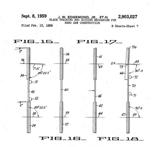
- Bandsaw Patent 15 -18.jpg (38.55 KiB) Viewed 867 times
As they say - a picture is worth a thousand words. I understand the drawings and the position of the Upper Wheel relative to the Lower Wheel and the Main Frame Assembly. I find it a very user friendly system for tracking on the Magna/Shopsmith Bandsaws. After using my Shopsmith Bandsaw I don't ever want to use another brand of Bandsaw again. The Craftsman I had before was a pain to get adjusted and tracking correctly by comparison to the Magna/Shopsmith Bandsaw. Hopefully all of this pieced together helps others understand also.
I do know that there is often some "tweaking" done to tools after the patent is applied for so that can explain any differences found in actual tools. I'm not sure if this happened in the case of the Bandsaw from drawings to actual manufacturing but we have seen changes through the years.