Shopsmiths 3" caster upgrade as it unfolds
Moderator: admin
-
ARCretired
- Gold Member
- Posts: 65
- Joined: Tue Apr 04, 2017 8:41 am
Re: Shopsmiths 3" caster upgrade as it unfolds
I installed the larger casters on a fairly new PowerPro machine & had to custom fit washers to get maximum clearance of the legs when the casters were fully down. This meant the casters were almost rubbing the floor when the legs were down. I believe the cam mechanism should be redesigned to provide more height. Haven't had time to look at the mechanism closely, but if the cam were to provide more height, then more force will be required at the lever to raise the machine because the overall mechanical advantage is changing. At some point friction becomes significant as well. We don't get the full advantage of the larger casters with the current mechanism. I have almost identical casters on a couple of benches and because there is no clearance problem with the bench bottom, everything rolls much easier (the bench is heavier than the SS).
-
JPG

- Platinum Member
- Posts: 35457
- Joined: Wed Dec 10, 2008 7:42 pm
- Location: Lexington, Ky (TAMECAT territory)
Re: Shopsmiths 3" caster upgrade as it unfolds
This has been beaten to death, but it bears repeating since posts such as this keep reappearing.
Some pertinent facts.
The cam has two lobes that raise the entire she bang in two 1/4" steps.
When the legs are resting on the floor(no weight on the casters) the slop in the caster post/rings allow the wheels to rest on the floor.
Since that slop must be first taken up, the first cam lobe raises the legs off the floor slightly less than 1/4".
The second lobe raises the legs an additional 1/4" off the floor.
Now since that vertical slop is small, the location of the caster mounting holes on the legs is critical.
When the mother ship released the larger caster upgrade they were entirely too sloppy with assuring that us plebes out in the wilderness would get those holes in the correct place(I be assuming 'they' knew where that was to begin with). They even sent 'us' xeroxed copies of the templates that were 'dimensionally challenged').
So much confusion has ranged and cam redesign comments are common. What has been missing is close attention to detail(where do the new holes need to be positioned, and how to get them there accurately).
Adding to all this is the historical confusion the SS literature has been inconsistent in describing the lift action.
One thing definitely has been constant since the model 10 caster days. The cam lobes are +1/4 and +1/2. The cams mounting has varied, but the lobes have not.
Now about the foot pedal location oversight!!!!
BTW if a washer can be inserted over the post and the weight of the SS still rests on the legs when casters are raised, the caster assembly is mounted too high to begin with.
╔═══╗
╟JPG ╢
╚═══╝
Goldie(Bought New SN 377425)/4" jointer/6" beltsander/12" planer/stripsander/bandsaw/powerstation /Scroll saw/Jig saw /Craftsman 10" ras/Craftsman 6" thicknessplaner/ Dayton10"tablesaw(restoredfromneighborstrashpile)/ Mark VII restoration in 'progress'/ 10E[/size](SN E3779) restoration in progress, a 510 on the back burner and a growing pile of items to be eventually returned to useful life. - aka Red Grange
-
dusty

- Platinum Member
- Posts: 21481
- Joined: Wed Nov 22, 2006 6:52 am
- Location: Tucson (Wildcat Country), Arizona
Re: Shopsmiths 3" caster upgrade as it unfolds
The location of the holes is critical to the first lift. If the holes are too high, that first lift might be inadequate is your floors are anything less than smooth. That said, there is very little you can do to alter the second lift.
I acquired my first set of 3" wheels very shortly after they were first offered. I did not utilize the template but I did use the dimensions shown on the template. My 3" casters work just fine. When lifted just one time, the lefts occasionally drag as a move the Mark V around the shop but they do work. Lifted to the second level they work as advertised.
BTW I just ordered another set and I intend to drill for them in exactly the same locations.
Some people reported having had problems but I suspect that some reports were inaccurate.
"Making Sawdust Safely"
Dusty
Sent from my Dell XPS using Firefox.
Dusty
Sent from my Dell XPS using Firefox.
-
ARCretired
- Gold Member
- Posts: 65
- Joined: Tue Apr 04, 2017 8:41 am
Re: Shopsmiths 3" caster upgrade as it unfolds
I should have mentioned that the alternative holes for the caster upgrade were already drilled by SS in my PowerPro machine. I still needed to add washers to maximize the lift for the best clearance to the floor with the caster upgrade. Having a slightly different hole location would have eliminated the need for spacers, however I suspect that the tolerances involved mean the hole locations can't be optimum for every assembly.
As far as the cam and mechanism design, the reason the cam has 3 locations is probably due to the foot operated lever actuation. 120 deg (3 positions in a full rotation) is as far as could reasonably be utilized in the available space and to have a lever reachable by foot in all three positions. The force required to actuate the pedal (if there were only 2 locations at 180 deg apart - an UP and DOWN) would likely be too great, unless the arms were longer - again too much space is required, and accessibility probably wouldn't work. Other types of mechanisms would probably be more complex - say a rack & ratcheting pinion. The SS design is clever, we just have to deal with the tolerance adjustment, or careful hole location if you drill them. And even larger casters with more clearance will still not roll over every obstacle. So fairly clean floors are a good habit anyway.
When I roll my SS out of the garage and into the driveway during warm weather, I have to lift each end for a few inches so the rollers won't fall into the transition crack. not too big a deal. Would be if the SS weighed a lot more - but the design is fairly weight efficient. I couldn't do that with a lot of stand-alone equipment.
-
dusty
- Platinum Member
- Posts: 21481
- Joined: Wed Nov 22, 2006 6:52 am
- Location: Tucson (Wildcat Country), Arizona
Re: Shopsmiths 3" caster upgrade as it unfolds
Shopsmith has published an addendum to the installation instructions and now issue four washers (about 1/16" thick) to be used to adjust the height. They speak of manufacturing tolerances introducing the possible need for these washers.
If the holes are located in the proper locations, please tell me where the manufacturing tolerance deviations come from. The plunger (503813) rests on the top of the caster. The other end of the plunger contacts the cam lobes.
I just today received a caster set (556224) from Shopsmith and I have a second set on order from another vendor. I am anxious to make some measurements on these eight casters just to be able to answer that question for myself. However, others thought would be appreciated.
"Making Sawdust Safely"
Dusty
Sent from my Dell XPS using Firefox.
Dusty
Sent from my Dell XPS using Firefox.
-
ARCretired
- Gold Member
- Posts: 65
- Joined: Tue Apr 04, 2017 8:41 am
Re: Shopsmiths 3" caster upgrade as it unfolds
Probably a lot of small tolerances. Let's call the distance from the bottom of the caster wheel (when the caster is pushed up tight in the UP position) to the bottom of the SS metal leg Dimension A. Let's call the height of the SS leg off the floor when the caster is in the full DOWN position - Dimension B. Dimension C is the full vertical travel of the caster from UP to full DOWN. C = A + B. I'll guess the cam tolerances are pretty small. There are caster stem to bottom of the caster wheel tolerances (wheel diameter, stem length, bearing slop, bearing cage stamping tolerances, etc). Then the tolerance of the drilled hole in the SS leg to the bolt fastener diameter, and the hole location relative to the bottom of the leg (leg is stamped metal, so stamping tolerances, hole location tolerances), Bolt hole location to the cam centerline in the mechanism, etc. Most of these tolerances are pretty small, but there are probably a few that cause most of the tolerance variation.
Measure how far the caster moves from full UP to full DOWN with each mechanism. (that's dimension C). More is better. Assemble each to a leg & measure A. The difference is how much clearance to the floor you will have in full DOWN caster position (dimension B).
I'm almost surprised that a 1/16" washer is enough in some cases. I believe the washers I added were a little thicker - but haven't measured them.
-
ARCretired
- Gold Member
- Posts: 65
- Joined: Tue Apr 04, 2017 8:41 am
Re: Shopsmiths 3" caster upgrade as it unfolds
One more thing. I put washers on the casters so that Dimension A was fairly close to 0 (zero). That meant the caster was resting on the floor when it was UP - but not carrying any of the SS weight. That let almost the full vertical travel (C) of the casters to be used to raise the legs, and provide max clearance to the floor. I believe this is what JPG's post said is the desired location. I couldn't re-drill the holes since they would have overlapped the existing holes already provided, so had to use washers.
-
robinson46176

- Platinum Member
- Posts: 4182
- Joined: Mon Mar 09, 2009 9:00 pm
- Location: Central Indiana (Shelbyville)
Re: Shopsmiths 3" caster upgrade as it unfolds
Here is another little caster wrinkle... 
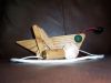
A good number of years ago now I was shopping in the Shopsmith factory store (I miss that store) and found a bin of casters that had been barely used and then pulled and I supposed replaced. I always figured that they may have been used on demonstration units and then replaced rather than sell demonstrators with scratched up casters (pictured below). The sign indicated that they would fit all then current models. The most interesting thing on the sign was the price... .50 cents each.
 I think I bought all of them in the bin, about 25.
My 10-ER was dragging on the floor too much and it had the old steel casters on it. They didn't roll all that well and had obviously been around the block a few times and were a little less than round. If I am remembering right they were about 1 7/8" in diameter. I replaced the steel casters with a set of these "new" ones and it has rolled great ever since. I still have those steel casters "somewhere". I know I didn't throw them away...
")

All of the rest of the casters on my Shopsmith's seem to be 2" in diameter and flat on the face. These I bought at the factory store have a decided crown to the floor face and measure maybe just over 2 1/8" The crown seems to make them swivel a lot easier. Do new SS casters today have a crown?
I move my 510 around fairly often and I also give the double drill press a shove or pivot pretty regular so it needs to be easy. The rest tend to sit by a spot against a wall or next to a post so they don't have to be that easy to move.
My basement floor is quite smooth and easy to roll stuff on but if I wanted to roll one outside of the door I would have to have wheel barrow wheels and tires on it. That is #2 crushed stone out there. Ranges from ping pong ball size up to tennis ball size, all with a lot of sharp corners. It's like that for fast drainage and it works excellent. It's about 2' deep and has a drain tile under it about 4 feet down. Not good with casters though.
Last week I was moving my 510 and it was not cooperating as well as I like so I am going to swap out its casters (I will still keep the old ones ). I hope it does as well as the 10-ER. It is a bit hard to judge completely on such a swap since I would not just change them but would fully service (clean and lubricate) the whole caster set at the same time.
A good number of years ago now I was shopping in the Shopsmith factory store (I miss that store) and found a bin of casters that had been barely used and then pulled and I supposed replaced. I always figured that they may have been used on demonstration units and then replaced rather than sell demonstrators with scratched up casters (pictured below). The sign indicated that they would fit all then current models. The most interesting thing on the sign was the price... .50 cents each.
My 10-ER was dragging on the floor too much and it had the old steel casters on it. They didn't roll all that well and had obviously been around the block a few times and were a little less than round. If I am remembering right they were about 1 7/8" in diameter. I replaced the steel casters with a set of these "new" ones and it has rolled great ever since. I still have those steel casters "somewhere". I know I didn't throw them away...
All of the rest of the casters on my Shopsmith's seem to be 2" in diameter and flat on the face. These I bought at the factory store have a decided crown to the floor face and measure maybe just over 2 1/8" The crown seems to make them swivel a lot easier. Do new SS casters today have a crown?
I move my 510 around fairly often and I also give the double drill press a shove or pivot pretty regular so it needs to be easy. The rest tend to sit by a spot against a wall or next to a post so they don't have to be that easy to move.
My basement floor is quite smooth and easy to roll stuff on but if I wanted to roll one outside of the door I would have to have wheel barrow wheels and tires on it.
Last week I was moving my 510 and it was not cooperating as well as I like so I am going to swap out its casters (I will still keep the old ones
- Shopsmith casters.jpg (58.89 KiB) Viewed 12876 times
--
farmer
Francis Robinson
I did not equip with Shopsmiths in spite of the setups but because of them.
1 1988 - Mark V 510 (bought new), 4 Poly vee 1 1/8th HP Mark V's, Mark VII, 1 Mark V Mini, 1 Frankensmith, 1 10-ER, 1 Mark V Push-me-Pull-me Drillpress, SS bandsaw, belt sander, jointer, jigsaw, shaper attach, mortising attach, TS-3650 Rigid tablesaw, RAS, 6" long bed jointer, Foley/Belsaw Planer/molder/ripsaw, 1" sander, oscillating spindle/belt sander, Scroll saw, Woodmizer sawmill
-
JPG
- Platinum Member
- Posts: 35457
- Joined: Wed Dec 10, 2008 7:42 pm
- Location: Lexington, Ky (TAMECAT territory)
Re: Shopsmiths 3" caster upgrade as it unfolds
I am curious what the c-c distance is between the two sets of holes in the power pro model. i.e. the distance above the lowest hole is to the next one up.(c-c)ARCretired wrote:I should have mentioned that the alternative holes for the caster upgrade were already drilled by SS in my PowerPro machine. I still needed to add washers to maximize the lift for the best clearance to the floor with the caster upgrade. Having a slightly different hole location would have eliminated the need for spacers, however I suspect that the tolerances involved mean the hole locations can't be optimum for every assembly.
As far as the cam and mechanism design, the reason the cam has 3 locations is probably due to the foot operated lever actuation. 120 deg (3 positions in a full rotation) is as far as could reasonably be utilized in the available space and to have a lever reachable by foot in all three positions. The force required to actuate the pedal (if there were only 2 locations at 180 deg apart - an UP and DOWN) would likely be too great, unless the arms were longer - again too much space is required, and accessibility probably wouldn't work. Other types of mechanisms would probably be more complex - say a rack & ratcheting pinion. The SS design is clever, we just have to deal with the tolerance adjustment, or careful hole location if you drill them. And even larger casters with more clearance will still not roll over every obstacle. So fairly clean floors are a good habit anyway.
When I roll my SS out of the garage and into the driveway during warm weather, I have to lift each end for a few inches so the rollers won't fall into the transition crack. not too big a deal. Would be if the SS weighed a lot more - but the design is fairly weight efficient. I couldn't do that with a lot of stand-alone equipment.
BTW the lobes and the foot pedal 'levers' are not 120° apart. Closer t0 90 90 180.
╔═══╗
╟JPG ╢
╚═══╝
Goldie(Bought New SN 377425)/4" jointer/6" beltsander/12" planer/stripsander/bandsaw/powerstation /Scroll saw/Jig saw /Craftsman 10" ras/Craftsman 6" thicknessplaner/ Dayton10"tablesaw(restoredfromneighborstrashpile)/ Mark VII restoration in 'progress'/ 10E[/size](SN E3779) restoration in progress, a 510 on the back burner and a growing pile of items to be eventually returned to useful life. - aka Red Grange
╟JPG ╢
╚═══╝
Goldie(Bought New SN 377425)/4" jointer/6" beltsander/12" planer/stripsander/bandsaw/powerstation /Scroll saw/Jig saw /Craftsman 10" ras/Craftsman 6" thicknessplaner/ Dayton10"tablesaw(restoredfromneighborstrashpile)/ Mark VII restoration in 'progress'/ 10E[/size](SN E3779) restoration in progress, a 510 on the back burner and a growing pile of items to be eventually returned to useful life. - aka Red Grange
Re: Shopsmiths 3" caster upgrade as it unfolds
ARCretired wrote:Would be if the SS weighed a lot more - but the design is fairly weight efficient. I couldn't do that with a lot of stand-alone equipment.
Might help ya if you move the headstock all the way to the right end. Then lift the left end over the transition crack. Move the headstock all the way to the left end,Then lift the right end over the transition crack.
SS 500(09/1980), DC3300, jointer, bandsaw, belt sander, Strip Sander, drum sanders,molder, dado, biscuit joiner, universal lathe tool rest, Oneway talon chuck, router bits & chucks and a De Walt 735 planer,a #5,#6, block planes. ALL in a 100 square foot shop.
.
.
Bob
.
.
Bob