Page 1 of 10
My Newest Toy
Posted: Thu Sep 01, 2016 7:55 am
by dusty
A 10'" Sanding Disk and Setup Plate from Infinity Cutting Tools. It will never be used as a disk sander.
It is advertised to be flat to within .002". So far, I have no reason to doubt that. But before I do any Table Alignment changes, I have a few things I want to check out.
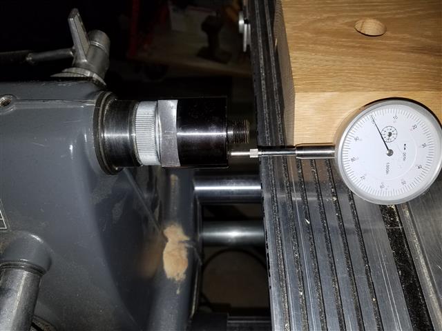
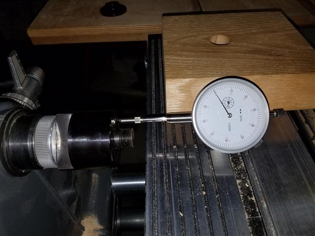
I have attached two new photo images. Please tell me what conclusions I can logically draw from the setup that you see here. The readings hardly change at all when I rotate the shaft.
- New Measuring Plate 013 (Small).jpg (66.52 KiB) Viewed 8863 times
- New Measuring Plate 015 (Small).jpg (61.87 KiB) Viewed 8863 times
Re: My Newest Toy
Posted: Thu Sep 01, 2016 8:25 am
by dusty
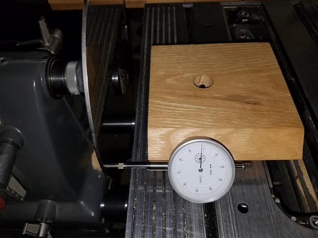
When I mount the plate and take measurements at the edge, the story changes somewhat.
Measuring on the infeed edge of the plate and rotating the disk slowly, the dial indicator changes from -.002" to +.002".
I think this indicates that the plate is introducing most of that change since the arbor measurements are so tight.
- New Measuring Plate 016 (Small).jpg (60.71 KiB) Viewed 8849 times
We are not going to discuss (at this time) what it looks like when I move the dial indicator to the far side of the blade and take a comparative measurement there. Table alignment then comes into question and the readings do not support what I believe table alignment is. Also in question is main drive shaft runout.
This plate may not be darn bit better than the Shopsmith Sanding Disk.
Re: My Newest Toy
Posted: Thu Sep 01, 2016 8:51 am
by wa2crk
Dusty
I think that the difference is caused by taking the readings at the outer edge of the disc for the reason that any small difference when taken at the arbor hub is magnified by the distance. Think of a rifle as opposed to a pistol. The longer sight picture of the rifle compensates for the error of the sight picture of the shorter pistol barrel.
When I align my 520 table I use the left hand miter gauge slot and lower the table so the dial indicator measures through the center of the blade and across the entire 10" of the blade. The better I can make the measurement at the outer rim the more accurate I am at the maximum cutting depth of the blade.
I hope I explained this correctly and adequately.
Bill V
PS Actually I think that the plate does meet specs. You are getting +.002 to -.002. If you set the gauge to a point on the disc where it reads 0 and rotate the disc and get your readings you do not exceed .002 so the plate could be said to meet the plus/minus .002 tolerance.
Re: My Newest Toy
Posted: Thu Sep 01, 2016 8:59 am
by Gene Howe
This plate may not be darn bit better than the Shopsmith Sanding Disk.
You're probably right, there.
Re: My Newest Toy
Posted: Thu Sep 01, 2016 9:01 am
by dusty
You explained it well even though I can not relate directly to rifle vs pistol sight alignment.
When I measure at the outer edge of the disk on the outfeed side and rotate it the measurements change from 0.0" to .004" (never going in the negative direction). Don't know yet if this means anything. Just recording test results. I did zero the dial indicator when it was reading maximum positive. Maybe if I zero when it is at minimum it will read differently. (This is an example of what I frequently refer to as technique.)
The online catalog states that "This disk is laser cut from the same premium steel plate that we use for our saw blades and is guaranteed to be within .002" flat".
Re: My Newest Toy
Posted: Thu Sep 01, 2016 9:08 am
by dusty
Gene Howe wrote:This plate may not be darn bit better than the Shopsmith Sanding Disk.
You're probably right, there.
That is really NOT the conclusion that I WANT to draw from this though it is looking likely.
Re: My Newest Toy
Posted: Thu Sep 01, 2016 9:58 am
by Gene Howe
I'd bet to get a flatter, dynamically balanced plate would be a heap of dough. Even then, unforeseen variables would likely crop up.
Re: My Newest Toy
Posted: Thu Sep 01, 2016 10:51 am
by JPG
Re: The initial question(etc.) and pix.
Re: The arbor adapter.
It appears the gauge is contacting the arbor adapter directly above and directly below the center axis of the shaft.
The lack of appreciable difference for either as the shaft is rotated implies the surface being 'tested' is 'normal' to the center axis of rotation.
The minimal difference between the two locations indicates the table top is parallel to the shaft axis.
Re: the flatness of the plate.
To my mind "Within 0.002" is not the same as "± 0.002". The latter is twice the deviation of the former.
Re: The runout at the periphery of the disk.
Rather than the rifle/pistol analogy, stick to simple ratios. If the plate surface is not consistently perpendicular to the axis of rotation, the gauge reading will vary. A reading taken with an identical setup closer to the center will be less by the ratio of the distance from the center. That however assumes the 'deviation' is linear from the center to the periphery. Considering the significant difference in the radius of the arbor adapter and the disc, a miniscule deviation at the arbor will indeed be much greater at the outside edge even if the plate were perfectly(linear) flat.
I assume your goal was to eliminate the need to rotate the reference surface(saw blade tooth/disc) when aligning the table slots to the shaft axis.
IMHO your reading ± 0.002 is adequate for that purpose regardless of the cause of that runout.
This ain't no machine shop tool Dusty.

Re: My Newest Toy
Posted: Thu Sep 01, 2016 1:27 pm
by dusty
JPG wrote:Re: The initial question(etc.) and pix.
Re: The arbor adapter.
It appears the gauge is contacting the arbor adapter directly above and directly below the center axis of the shaft.
The lack of appreciable difference for either as the shaft is rotated implies the surface being 'tested' is 'normal' to the center axis of rotation.
The minimal difference between the two locations indicates the table top is parallel to the shaft axis.
Re: the flatness of the plate.
To my mind "Within 0.002" is not the same as "± 0.002". The latter is twice the deviation of the former.
Re: The runout at the periphery of the disk.
Rather than the rifle/pistol analogy, stick to simple ratios. If the plate surface is not consistently perpendicular to the axis of rotation, the gauge reading will vary. A reading taken with an identical setup closer to the center will be less by the ratio of the distance from the center. That however assumes the 'deviation' is linear from the center to the periphery. Considering the significant difference in the radius of the arbor adapter and the disc, a miniscule deviation at the arbor will indeed be much greater at the outside edge even if the plate were perfectly(linear) flat.
I assume your goal was to eliminate the need to rotate the reference surface(saw blade tooth/disc) when aligning the table slots to the shaft axis.
IMHO your reading ± 0.002 is adequate for that purpose regardless of the cause of that runout.
This ain't no machine shop tool Dusty.
I know so very well that this ain't no machine shop. I can tell by the "sawdust".
You would be wise not to assume anything about "my goals". This is simply another one of my "toys".
This toy has the potential to become a key tool in my arsenal of alignment tools but at the moment it is not.
I could have/should have done a better job of selecting the images to post. Those first two images are with the dial indicator at 3 and 9. Same difference with regard to your comments however.
I appreciate the feedback.
Re: My Newest Toy
Posted: Thu Sep 01, 2016 1:49 pm
by everettdavis
What are the incremental readings measured from the same point on the work table, at 12", compared to 11", 10" and so on?
Most expressions of a .002" variance (such as those for the plate itself) would be over some known fixed distance.
Take the disk and arbor to a machine shop and have them measured on far more precise equipment to know what you are using as a reference may introduce into your results.
Now enter the Quill, the bearings, and the shaft itself, for possible other variances.
With your dial indicator in a fixed position, what happens when you introduce a bit of pressure left to right on the disk just above the measurement point? That would be a run-out measurement with the Quill retracted and locked down.
Now unlock the Quill and measure it.
Next extend and lock the Quill and measure it.
Now move the dial indicator and table to position it at 12:00 on the disk.
Introduce a bit of pressure left to right on the disk just in front of the measurement point.
Now unlock the Quill and measure it at 12:00.
Next extend and lock the Quill and measure it at 12:00.
All of the additional variances you see are in the Quill housing, the shaft, and bearings, none of which were intended to be manufactured to .001 inch tolerances, though some could be close to that and others have a good bit of variance from the OEM and still be in specifications for the aluminum headstock which will have some variances in it due to what temperature it is measured at.
To prove that, run the jointer on the other end and do enough work to heat up the headstock and repeat the measurements.
I have found an additional variance sometimes exists when an SPT is connected by the coupler on the other end of the shaft and the bearings are worn some in the Quill, compared to being disconnected from the headstock.
The 10E and 10ER were made with closer tolerances with the cast iron headstock.
Where did you say you acquired you Newest Toy? I may want one myself.
At one point I had considered having some stock milled to the exact width of the miter gauge slot and a hole bored through it to mount on a known true 5/8 molding arbor to use in table alignments, but haven't done that yet.
It would eliminate the dial indicator for that segment, but using the edge of the table itself (after first verifying it is exactly parallel to the miter slots) allows me to square it to the known true sanding disk and I am done. Rotating the table to 90 degrees and mating it up to the sanding disk allows me to set the levelness of the table itself, and prepare to set my zero point with a machinists square by setting the 90 degree point when the table and disk are parallel.
Everett