Page 1 of 3
Motor Wiring
Posted: Wed Feb 07, 2018 12:00 am
by dzawacki
Okay, so electricity is not my forte and I'm not sure if I'm going to be able to post a clear description of what my problem is or if anyone will be able to help me via the forum, but it's worth a shot!
I got a free ShopSmith 10ER off Craigslist and it came with a 3/4hp motor on it. My existing ShopSmith 10ER has a 1/2hp motor on it. So clearly, I need a bigger motor.
On my existing ShopSmith, the motor is wired to a switch that has a forward, off, and reverse position. This is what complicates the matter for me. If I was just swapping motors, it'd be a breeze to disconnect and connect the new.
The 3/4hp motor gives instructions on how to reverse the rotation of the motor, by swapping two wires inside the motor. I feel like this is something I should be able to do via the switch (but again, I don't know electrical too well).
What I've tried so far is to hook up two wires to the studs inside the 3/4hp motor, give power to the switch, and then touch the other ends of the wires to the switch while it was on to power the motor. I checked the rotation and then swapped which wires were touching where on the switch to swap the polarity. When I applied power in the new polarity, the motor spun in the same direction as before. Clearly, I didn't do what I wanted to do correctly.
So, I'm hoping if I post some pictures of the setup along with my dilemma, one of you great people might have some guidance to point me in the right direction via the forum. If you have the knowledge and are local to Madison, WI, shoot me a PM as well.
Thanks in advance!
Re: Motor Wiring
Posted: Wed Feb 07, 2018 12:30 am
by JPG
All 4 internal motor wires need to be connected to the switch. The switch must connect power across the white and black wires in both forward and reverse.
The switch must also connect the red and black wires to the white and black wires, but are reversed between forward and reverse.
I am unfamiliar with the switch pictured, but it has to have the on/off/on switching action for controling the power. Separately in must provide the flip of the red and black wires.
The pix on the switch only reveals 6 terminals, but the wire count coming from the 4 power cords is more than twice that. Are there other terminals that are not visible? Is there an addition copper part similar to the one in the pix, but on the reverse side?
Re: Motor Wiring
Posted: Wed Feb 07, 2018 7:32 am
by BuckeyeDennis
dzawacki wrote:Okay, so electricity is not my forte and I'm not sure if I'm going to be able to post a clear description of what my problem is or if anyone will be able to help me via the forum, but it's worth a shot!
I got a free ShopSmith 10ER off Craigslist and it came with a 3/4hp motor on it. My existing ShopSmith 10ER has a 1/2hp motor on it. So clearly, I need a bigger motor.
On my existing ShopSmith, the motor is wired to a switch that has a forward, off, and reverse position. This is what complicates the matter for me. If I was just swapping motors, it'd be a breeze to disconnect and connect the new.
The 3/4hp motor gives instructions on how to reverse the rotation of the motor, by swapping two wires inside the motor. I feel like this is something I should be able to do via the switch (but again, I don't know electrical too well).
What I've tried so far is to hook up two wires to the studs inside the 3/4hp motor, give power to the switch, and then touch the other ends of the wires to the switch while it was on to power the motor. I checked the rotation and then swapped which wires were touching where on the switch to swap the polarity. When I applied power in the new polarity, the motor spun in the same direction as before. Clearly, I didn't do what I wanted to do correctly.
So, I'm hoping if I post some pictures of the setup along with my dilemma, one of you great people might have some guidance to point me in the right direction via the forum. If you have the knowledge and are local to Madison, WI, shoot me a PM as well.
Thanks in advance!
JPG is a master at this stuff — he will definitely be able to get you hooked up correctly.
I really like that cool old drum switch you have, and would like to find a similar switch for my own vintage machines .. the knob looks identical to ones on my 50’s vintage DeWalt radial arm saws. Does your switch have a manufacturer and model number on it somewhere?
Whilst Googling for similar switches, I happened across a video explaining how to wire up a modern reversing drum switch. It might help you better understand JPG’s instructions.
[youtube]
https://m.youtube.com/watch?v=ilpKrdvQkQA[/youtube]
Re: Motor Wiring
Posted: Wed Feb 07, 2018 9:55 am
by dzawacki
The switch is a Dayton brand. I didn't see a model number on it, the label was covered by some tape to mark forward and reverse.
Re: Motor Wiring
Posted: Wed Feb 07, 2018 9:57 am
by dzawacki
JPG wrote:All 4 internal motor wires need to be connected to the switch. The switch must connect power across the white and black wires in both forward and reverse.
The switch must also connect the red and black wires to the white and black wires, but are reversed between forward and reverse.
I am unfamiliar with the switch pictured, but it has to have the on/off/on switching action for controling the power. Separately in must provide the flip of the red and black wires.
The pix on the switch only reveals 6 terminals, but the wire count coming from the 4 power cords is more than twice that. Are there other terminals that are not visible? Is there an addition copper part similar to the one in the pix, but on the reverse side?
JPG, thanks for the info. I'll see if I can get some better pictures of the switch after work tonight.
I think I'm starting to follow what you said. I might have to draw up what I understand and see if that aligns with what you're saying.
Re: Motor Wiring
Posted: Wed Feb 07, 2018 10:16 am
by JPG
BuckeyeDennis wrote:
Whilst Googling for similar switches, I happened across a video explaining how to wire up a modern reversing drum switch. It might help you better understand JPG’s instructions.
[youtube]
https://m.youtube.com/watch?v=ilpKrdvQkQA[/youtube]
That video also helped JPG understand how the drum switch works!

Now he knows what to tell him.

Re: Motor Wiring
Posted: Wed Feb 07, 2018 10:30 am
by JPG
It would be helpful to verify switch operation if pix were posted showing the switch in both forward and reverse positions.
Re: Motor Wiring
Posted: Wed Feb 07, 2018 10:56 am
by dzawacki
That makes sense, I can grab some photos of the forward and reverse positions this evening.
Thanks!
Re: Motor Wiring
Posted: Wed Feb 07, 2018 2:10 pm
by reible
Noticed the ground wire is cut so it is questionable if the ground is carried to the location those wires are going.... First circle to the left.
It looks like an excessive amount of wear on the contacts, is that normal for these switches? We used rotatory switches in the telephone projects but never the voltage or currents involved with this sort of motor.
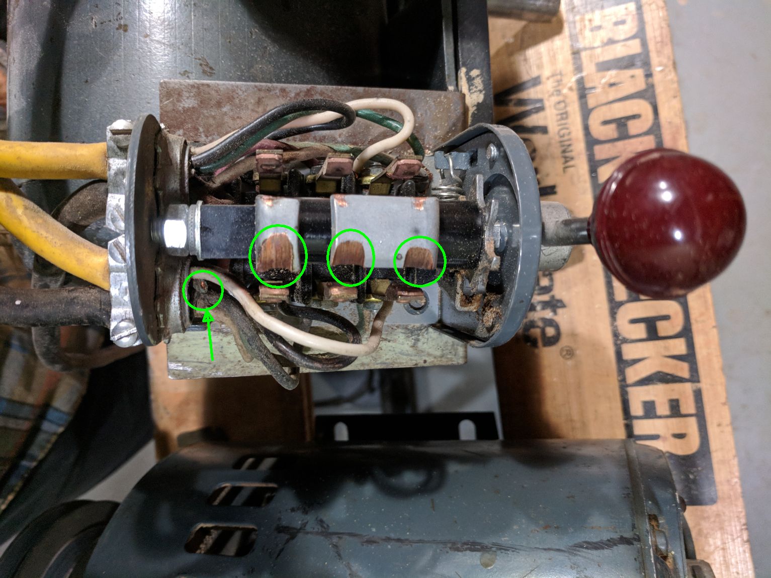
- Clipboard01.jpg (247.6 KiB) Viewed 8320 times
Ed
Re: Motor Wiring
Posted: Wed Feb 07, 2018 3:37 pm
by Hobbyman2
Looks like a good place for a OHMS meter.