JPG wrote:Bearing retainer clip(s) should be on the yellow line???
I looked to see if Thundderbirdbat's single clip was oem.
James you are correct.
It isn’t there because it wasn’t there initially in the original machine, or in the drawing in the original manual.
I had noticed that too, as it was not part of the Original 1954 drawing, and it did not appear in the numerical parts listing for this direct drive version of the 1954 Mark 5 manual.
As our late friend Bill Mayo and I had discussed some years ago, it was developed to solve a problem they only found after they introduced it.
This brings back into focus the Gilmer Clutch update that also occurred after the initial manual but before the patent was applied for. It too would have been a production change, before patent.
I have not found a Shopsmith bulletin announcing the bearing retainer or the clutch, however I am still looking. Perhaps you can better understand why I put out a Call for Document Submissions. I would like to find a copy of both production change announcements if surviving copies exist.
This indicates that it was not part of the original machines and added as production change, before the actual patent application and drawings were made and submitted in 1955.
The inset side view drawing I added in the redrawn exploded parts diagram had the retainer, but it also came from a later drawing. It too was not the patent drawing as it did not have the clutch. The patent drawing had it in 1955.
We know Shopsmith introduced the Mark 5 in 1954, (they referred to it as an M5 in the manual) and retainer is item 104 in the Patent Drawing, not the original manual.
I am toying with a version two of the exploded parts diagram in which I might break out a highlighted circle to illustrate both the bearing retainer and the clutch for the Gilmer drive.
My drawing will appear at the end of the original manual. It will have the original drawing as Page 25.
Shopsmith Patent 2,927,612 was filed: March 15, 1955 and granted March 8, 1960 almost 5 years later.
Verbiage in the patent application, and the illustration of the retainer is in the patent application.
Fixed to the shaft 164 outwardly of and adjacent the pulley 166 by a set screw 173 is a stepped hub or sleeve 74 and keyed by external gear teeth to the stepped end of this sleeve, and which is circumscribed by the outer end of the pulley 166, is a series of steel rings 175 alternated with the annular fiber rings 172 and forming a friction clutch therewith. As a result of this construction it will be seen that the only connection between the pulley 166 and the drive shaft 164 is through the spring pressed alternated fiber and steel rings 172 and 175 and that if too great a load is imposed on the shaft ió4 slippage will occur between the two sets of friction rings.
Reference the side-by-side drawings below.
Everett
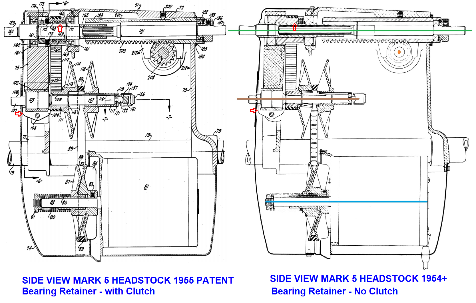
- 1954 Side View compared to 1955 Side View filed with Patent.png (663.34 KiB) Viewed 8018 times

