Page 1 of 2
Installing 505/10/20 Crank on 500 table lift
Posted: Sun Mar 29, 2009 7:04 pm
by JPG
This is verbally described deep in another thread, but I thought it needed a better description and its own thread.
The first pic is the table lift crank with lever disassembled. (BEFORE)
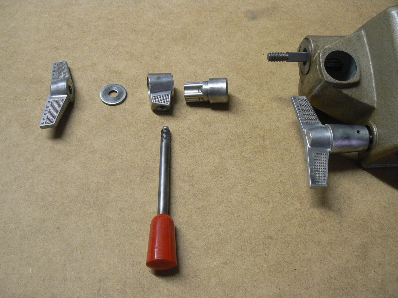
- b4 table lever.jpg (363.52 KiB) Viewed 21487 times
The second pic shows the assembly sequence of 'new' lift crank. (AFTER)
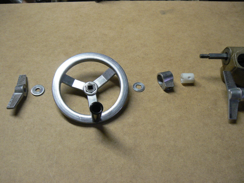
- after crank.jpg (345.12 KiB) Viewed 21497 times
The third pic shows the NEW parts. The crank(514330) is NOT shown.
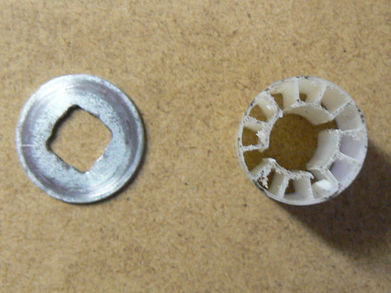
- new parts.jpg (327 KiB) Viewed 21482 times
The washer is a 3/8" flat washer which will not quite fit over the crank shaft. Therefore the 4 notches are added(filed).
The white thingey is a spacer to hold the original 'pinion knob' centered. It is made from a paper roll core and is slightly shorter than the pinion knob. The core had 8 webs between the od(7/8") and the id. The id was 'sliced' at 4 places equally spaced. This allows the 'thingey' to slip over the crank shaft.
The washer goes between the new crank and the original pinion knob. The clamping force when the lock wingnut is tightened is from the crank through the washer to the pinion knob and to the table pinion.
The fourth pic shows the spacer(thingey) on the crank shaft.
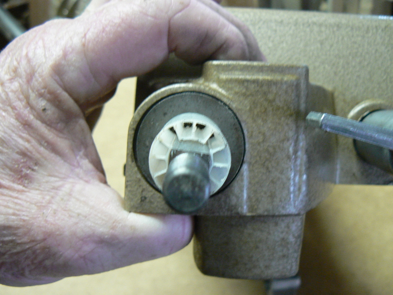
- spacer on shaft.jpg (290 KiB) Viewed 21487 times
The last pic shows the downside to this alteration.
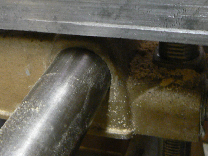
- hit crank limit.jpg (285.74 KiB) Viewed 21486 times
When the table is rotated 90°(think vertical drill press) the table hits against the crank 7/8" short of hitting the way tubes(previous limit).
This 'alteration' does NOT modify any existing parts and is therefore totally reversible(assuming you keep track of the newly unused parts).

EDIT: 'Thingy' has been replaced with a more durable part.
http://www.shopsmith.com/ss_forum/viewt ... 20#p163020
Also see other(simpler) solution below.
Posted: Sun Mar 29, 2009 8:48 pm
by a1gutterman
That was a great illustrated description of the conversion. I purchased a 1995 510 new, so this does not effect me, but for those interested, what outside diameter is the paper roll core "thingey"?
Posted: Sun Mar 29, 2009 9:42 pm
by JPG
a1gutterman wrote:That was a great illustrated description of the conversion. I purchased a 1995 510 new, so this does not effect me, but for those interested, what outside diameter is the paper roll core "thingey"?
7/8" Thank You:) I added that 'detail' above.

Posted: Mon Mar 30, 2009 6:28 pm
by nuhobby
Cool posting!
I was also curious, if anyone has tried on a model 500 just putting the table-height lever pieces on the opposite side of the carriage. It is no longer next to the carriage-lock handle, but it seems to have less mechanical interference with the table back there. (I'm going by memory and haven't tried it again, but I think that one time I tried it, it worked fine!)
Posted: Mon Mar 30, 2009 9:18 pm
by JPG
nuhobby wrote:Cool posting!
I was also curious, if anyone has tried on a model 500 just putting the table-height lever pieces on the opposite side of the carriage. It is no longer next to the carriage-lock handle, but it seems to have less mechanical interference with the table back there. (I'm going by memory and haven't tried it again, but I think that one time I tried it, it worked fine!)
The crank shaft can be reversed. Whether it clears the table 'better' ? I shall try it and SEE!
YEP It totally clears the table in 'vertical mode'. The rip fence could get in the way. The table 'hangs out' less in the back than the front. I did NOT try it in horizontal mode but it would also be 'better'. It may be more convenient to have the handle on that side when 'drill pressing' anyway.
Great idea!
Posted: Sat Mar 08, 2014 11:49 am
by teacherman
nuhobby wrote:Cool posting!
I was also curious, if anyone has tried on a model 500 just putting the table-height lever pieces on the opposite side of the carriage. It is no longer next to the carriage-lock handle, but it seems to have less mechanical interference with the table back there. (I'm going by memory and haven't tried it again, but I think that one time I tried it, it worked fine!)
I think that is a great idea. I already noticed I have to unscrew the handle far enough to wiggle it around the lock knob.I may try to put it on the other side. I'm trying to think if that would interfere with any other usage, but I am so new to this, my thinking is more dreaming than anything else.....

Posted: Sat Mar 08, 2014 12:18 pm
by JPG
teacherman wrote:I think that is a great idea. I already noticed I have to unscrew the handle far enough to wiggle it around the lock knob.I may try to put it on the other side. I'm trying to think if that would interfere with any other usage, but I am so new to this, my thinking is more dreaming than anything else.....
Nothing wrong with a functioning imagination(dreaming, no). Therein lies the seeds of innovation.
For any one who cares, the paper roll core has been replaced with a 'shopsmith part' of unknown origin(to the seller) but known to the buyer(me) that was made by sawing off(by an unknown individual for an unknown purpose) the clover leaf shaped part of the hub that the lever normally detents into. Just the right length etc.! Not that I was concerned about the paper roll's durability, but it is better and really really less Rube Goldbergy.
BTW, The move to opposite side(rear) does work!(IIRC)
Re: Installing 505/10/20 Crank on 500 table lift
Posted: Wed Mar 09, 2016 8:57 pm
by jjbuzard
For the spacer I used a 12 point 3/8 drive 9/16 cheap socket. Perfect length.
Re: Installing 505/10/20 Crank on 500 table lift
Posted: Wed Mar 09, 2016 9:02 pm
by JPG
jjbuzard wrote:For the spacer I used a 12 point 3/8 drive 9/16 cheap socket. Perfect length.
See I too believe in 'personalization'!

Re: Installing 505/10/20 Crank on 500 table lift
Posted: Thu Mar 10, 2016 5:04 pm
by jjbuzard
Back in about 1996 I came up with this way to approach this problem, I went to a ShopSmith Store, what were they "Woodworking Unlimited" and and asked them if the new wheel handle to raise and lower the table on my Mark 5, they said "NO." So I went over and looked at one on the showroom floor and when no one was looking I took the Handwheel off and looked it over, figured out what I needed to do to make it work and ordered the "Crank and Insert" and proceeded to make it work when it was delivered, I figured out the only thing I needed to do was inert a 3/8" drive 9/16" socket and put it back together. Below are the pictures that show how it works.
Here are the parts,
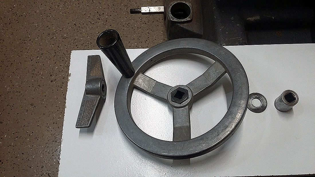
- Table Height Lock, Crank and Insert and washer along with 9/16" -12 point 3/8" drive socket
- Table 2.jpg (780.73 KiB) Viewed 20106 times
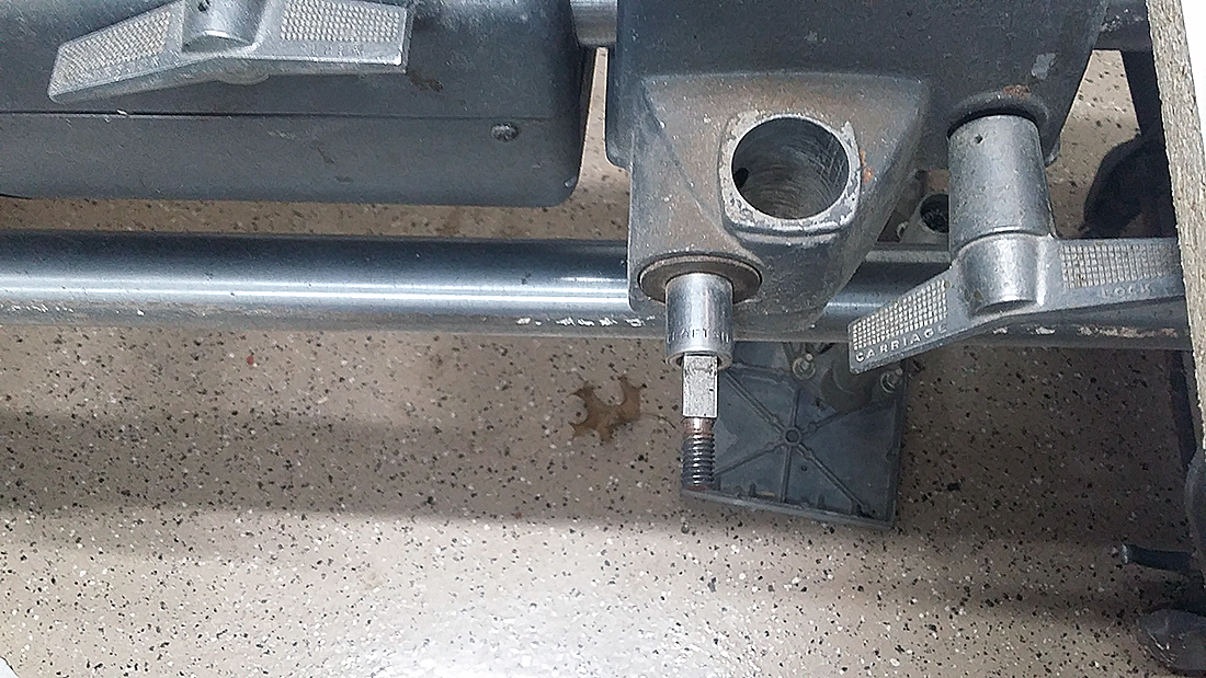
- Shows the 3/8" drive socket, which the socket drive socket is exactly the right size to fit over the Pinion shaft square end
- Table 1.jpg (805.57 KiB) Viewed 20106 times
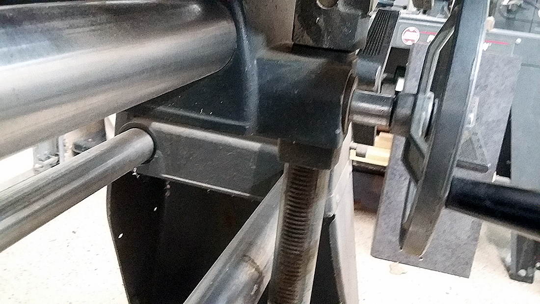
- Showing the table fully lowered to the way tubes.
- Table 4.jpg (809.18 KiB) Viewed 20106 times