Page 1 of 2
speed changer center bit stuck
Posted: Tue May 21, 2024 4:08 pm
by don1357
And I mean it is there as if it was never meant to move nor come out. The ends were pretty stuck as well, but a jaw puller did quick work of those. The center piece is not impressed by the jaw puller... The next stop would the the 12-ton press, but on an overabundance of caution I figure I would has here first. Is there a trick to this or is it just controlled brute force?
Re: speed changer center bit stuck
Posted: Wed May 22, 2024 12:23 pm
by chapmanruss
I had a floating center stuck on the sleeve as bad as the one you are describing. Yes, I ended up using my 12-ton press to get it off. Before using the press remove the oilite bearings first if you can, especially if they are still in good usable condition. These are brass and could be mushroomed out in the press. I have a bearing puller plate that is large enough and slopped to rest the center in when on the press. I use a wood block between the press and the sleeve just to avoid metal to metal contact there. A very good idea if the oilite bearings are still in the sleeve. Be ready to "catch" the sleeve when it "pops" loose to avoid it hitting the floor or other objects as it come out.
The probable cause of this is lack of proper lubrication. To help aid removal some penetrating oil applied well before using the press may be beneficial.
The sleeve and/or the inside of the floating center may be scarred. Some careful sanding to smooth out any ridges will help bring your Speed Changer back to life.
Re: speed changer center bit stuck
Posted: Wed May 22, 2024 3:45 pm
by don1357
Good call on removing the sleeve bearings. Is there a particular trick to remove them?
Re: speed changer center bit stuck
Posted: Wed May 22, 2024 4:31 pm
by Matanuska
chapmanruss wrote: Wed May 22, 2024 12:23 pm
I had a floating center stuck on the sleeve as bad as the one you are describing.
What are a “speed changer center bit” and a “floating center”? They sound related to lathe centers but I don’t get the speed changer & floating references. Can you educate me please?
Re: speed changer center bit stuck
Posted: Wed May 22, 2024 9:28 pm
by don1357
The speed changer has a pulley system where the center part 'floats'. As it goes back and forward, when one side gets bigger/smaller the other gets smaller/bigger.
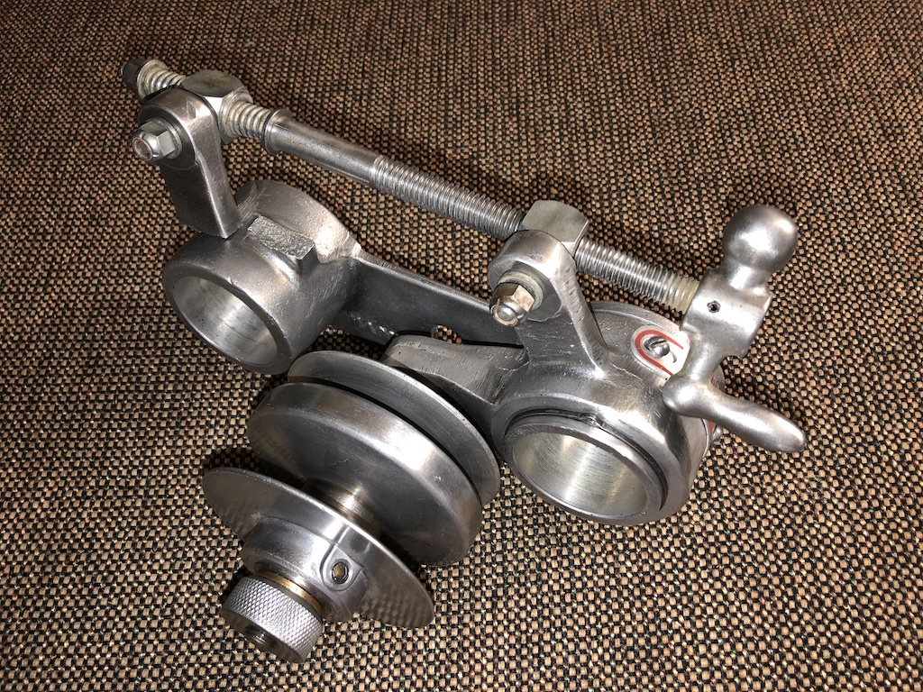
That bit right there in the middle of the double pulley system. The correct name is the floating sheave, but I don't think many know it by that. Heck probably not even people that own one. But if you do own one, any words around 'pulley' and 'middle' (thing, bit, whatchamacalit) would let you know what is being talked about.
Re: speed changer center bit stuck
Posted: Wed May 22, 2024 10:15 pm
by jsburger
don1357 wrote: Wed May 22, 2024 9:28 pm
The speed changer has a pulley system where the center part 'floats'. As it goes back and forward, when one side gets bigger/smaller the other gets smaller/bigger.
That bit right there in the middle of the double pulley system. The correct name is the floating sheave, but I don't think many know it by that. Heck probably not even people that own one. But if you do own one, any words around 'pulley' and 'middle' (thing, bit, whatchamacalit) would let you know what is being talked about.
Your description of how the speed changer works is correct. However, I saw your post before there were any replies and did not understand what the "middle bit" was so I did not reply. I have 5 10ER's here all with speed changers. We all know it as a floating sheave. Just like all MK 5's have a floating sheave. It is called a Reevs drive named after the inventor I believe. You did not mention Pulley in your original post so very confusing.
Re: speed changer center bit stuck
Posted: Wed May 22, 2024 10:24 pm
by Matanuska
don1357 wrote: Wed May 22, 2024 9:28 pm
That bit right there in the middle of the double pulley system. The correct name is the floating sheave, but I don't think many know it by that. Heck probably not even people that own one. But if you do own one, any words around 'pulley' and 'middle' (thing, bit, whatchamacalit) would let you know what is being talked about.
Thanks - that explains it!
Re: speed changer center bit stuck
Posted: Thu May 23, 2024 8:48 am
by nv10er
don1357 wrote: Wed May 22, 2024 3:45 pm
Good call on removing the sleeve bearings. Is there a particular trick to remove them?
I just removed the bronze bearings from my speed changer sleeve the other day by inserting a small section of 1/4” wood dowel through one end until it rests on the inside lip of one bearing, and then tap the other end of the dowel with a hammer. One was easy to remove, and one was not. Try both to see which one comes out easiest with the small dowel. Once you have one out, a larger 5/8” dowel can be inserted into the opening of the sleeve where the removed bearing was to allow more aggressive driving force to remove the second bearing.
Re: speed changer center bit stuck
Posted: Fri May 24, 2024 3:19 pm
by chapmanruss
It may be a good time for some Speed Changer 101.
In the picture don1357 posted above the main casting is broken. (see arrow in the copy of his picture below)
_
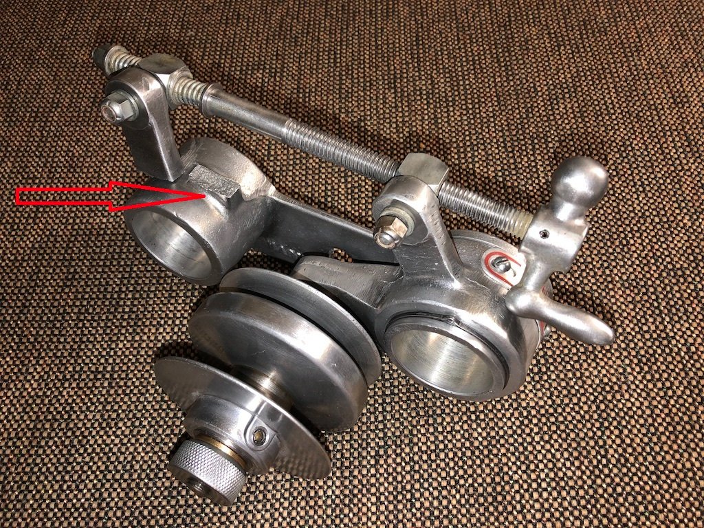
- Broken Speed Changer don1357 arrow.jpg (337.36 KiB) Viewed 2814 times
.
The arrow is pointing to the place on the main casting where the "ear" (above the arrow) has broken off. Cranking the Screw Assembly (speed adjustment) handle too far can cause the "ear" to break off the main casting. The handle should never be turned past the point the springs on the back end of the Screw Assembly begin to compress. At that point you will no longer change the speed but will risk damaging the Speed Changer. The lock nut on the end of the Screw Assembly should NOT compress the springs as it is in the example shown below. That nut should be backed off so the springs are not compressed.
_
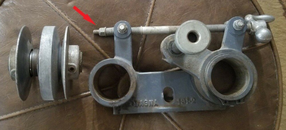
- Speed Changer nut tension arrow.jpg (91.31 KiB) Viewed 2814 times
.
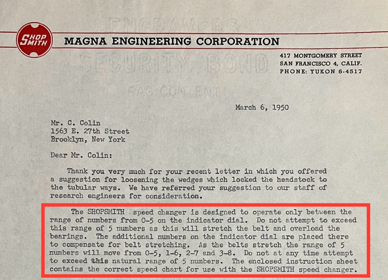
Early Speed Changers had a speed indicator with a 0 to 8 range while later Speed Changers had an indicator with a 0 to 5 range. With either indicator properly set, the speed range is only 0 to 5 and trying to go up to the 6 to 8 range on the early indicator will not increase the speed but will break the casting as shown above. I have no explanation as to why the early indicators had a 0 to 8 range.
_
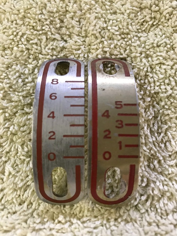
- Speed Changer indexs r.jpg (172.19 KiB) Viewed 2814 times
.
The other common breaking point of the main casting is through the center where the set screw goes through to hold it against the Headstock with the nut. The set screw holds the motor mount in the Headstock and should be tight, but the nut is only there to keep the Speed Changer in position against the Headstock. That nut does not need to be tight and if binding occurs while moving the Headstock on the way tubes the Speed Changer Main Casting can break through the middle. See caution in item 18 on page 1 in the PDF manual below.
The problem already discussed in this thread can be avoided by keeping the Floating Pulley Assembly properly lubricated. This includes lubricating the floating center sheave on the sleeve and the Assembly itself (brass bearings) on the shaft of the Pulley Arm. For this a light-weight oil works best and is the easiest to apply. The Pulley Arm needs to be kept lubricated on the Main Casting too. Some dry lubricant can be used on the Screw Assembly threads.
A PDF copy of a Variable Speed Changer Manual is available below
.
.
Page 2 items 4 & 5 must now be done yourself. Item 4 adjustment of the outer Pulley Sheaves of the Floating Pulley Assembly is accomplished by having one belt almost touching the inner sleeve while the other belt is even with the outer edge of the Pulley. The original belts supplied were 22-1/2" and 25-1/2" long but can be hard to find. 22" and 25" long belts work fine. Item 5 the oilite bearings (bushings) has been discussed in this thread already.
The pictures above of the Speed Changer shows the early way the Screw Assembly was mounted coming from the factory. The PDF manual on page 1 shows the later mounting position of the Screw Assembly which helps keep the handle (and your knuckles) from hitting the Headstock's Way Tube Lock.
The Variable Speed Changer is a popular accessory with users of the Shopsmith Model 10E and 10ER. There are only so many left in existence and care should be taken to avoid damage to them.
Re: speed changer center bit stuck
Posted: Sat May 25, 2024 8:20 am
by jpdalton
chapmanruss wrote: Fri May 24, 2024 3:19 pm
I have no explanation as to why the early indicators had a 0 to 8 range.
…then let’s ask the team at Magna Engineering!
.
- IMG_4169.jpeg (724.95 KiB) Viewed 2765 times
