Page 1 of 2
Oooops
Posted: Mon Dec 30, 2024 8:22 pm
by stihlsawer
I think I messed up! I was cleaning waxing my new to me '95 model 510 today. I ran the motor through the full speed range and it ran well. I had a very hard time getting the bottom drive hub off in order to oil the the shaft locations. I used WD-40, then Kroil, followed by heat while smacking the hub several times on each side with a mallet. I finally was able to get the hub off. I oiled the two locations and put the rear cover back on. I hand spun the shaft to move the control back to the slow position, but only made it to about the dado setting; it was starting to get tight. I thought I would just start it up and move through the speed settings, but only got hum. Turned it off quickly and let it set for a few minutes while spinning the shaft real slow. Tried it again and only hum! I was running out of daylight so unplugged and covered it. I wonder if I wasn't spinning the shaft fast enough while I was moving the speed control, causing it to bind?? OR my mallet smacking moved the belt positioning?? I will remove the rear cover tomorrow and check the belt pulley alignment and tension. What else should I do? Thank you.
Trever
Re: Oooops
Posted: Mon Dec 30, 2024 8:48 pm
by JPG
Manually pull the lower(motor) floating sheave so the pulley opens. This is not easy due to the spring tension, but should be possible. I think it is sticking.
Now WHY was the hub difficult to remove? Was the set screw NOT on the flat of the shaft? If the shaft is scored it needs to be cleaned up before reinstalling the hub.
Re: Oooops
Posted: Mon Dec 30, 2024 8:55 pm
by stihlsawer
I cleaned, waxed and buffed the shaft and it didn't slide on as it should. I suspect a wrong sized hub... I left it off. Something else to note, it came with two brand new saw arbors that are for a 500. I noticed the arbor that is attached to a combo blade is also for a 500. This is why I suspect a wrong hub size. The hub shafts are in good shape. The headstock's insides are clean. This machine was not used alot by the looks of it.
Re: Oooops
Posted: Mon Dec 30, 2024 8:56 pm
by stihlsawer
Oh sorry, it was on the flat.
Re: Oooops
Posted: Tue Dec 31, 2024 12:28 pm
by chapmanruss
I have to wonder if when removing the lower SPT Drive Hub you moved or possibly damaged the mounting of the Idler Drive Assembly. Do as JPG suggested to make sure the belt isn't bound up in the Motor Sheave. Below is the inside of the Belt Cover. Note the position of the Idler Shaft Assembly (lower Drive Shaft) and the Eccentric in the Headstock Casting mounting point. If yours is not even between the Headstock Mounting and the Idler Shaft Assembly including the Eccentric that could be the problem not being able to turn the Speed Control through the entire range.
_
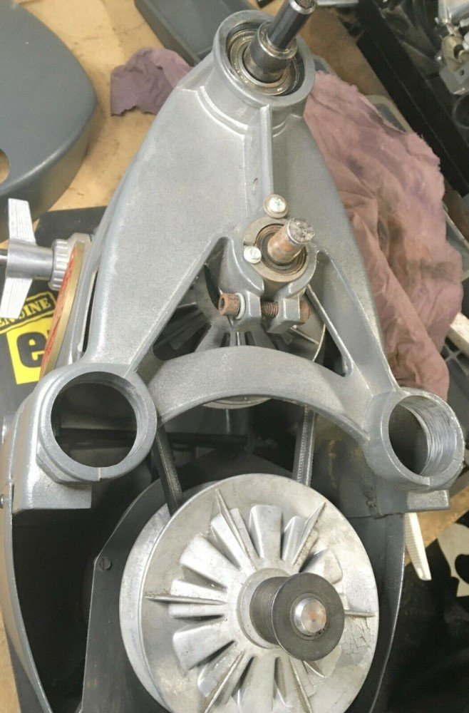
- inside belt cover.jpg (124.25 KiB) Viewed 2659 times
.
As for the Hub if it now slips on and off easily from the lower Auxiliary Drive (Idler Shaft Assembly) that problem is solved. There are two different size bore Hubs but are for the SPT's themselves. Some SPT's use a 5/8" bore hub while others use a 1/2" bore. Both Auxiliary Drive Shafts on the Headstock are 5/8" in diameter and an example of the Hubs in place is below. Ignore the arrows which point out the holes for mounting the Shaft Guard used for a different post.
_
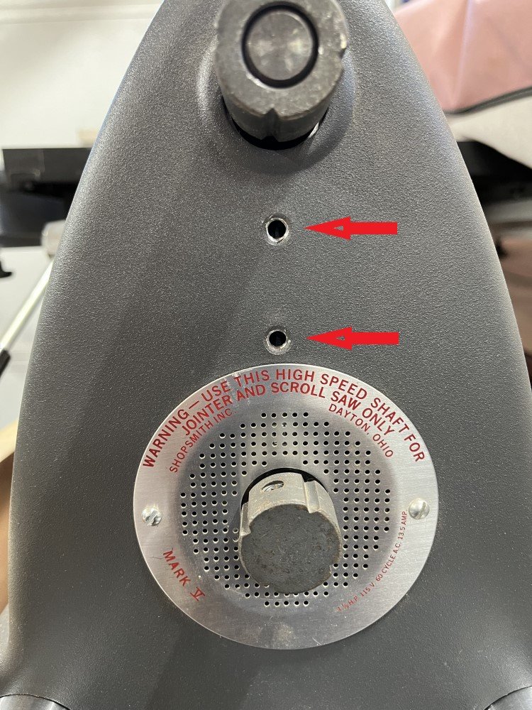
- Mounting Holes.jpg (221.81 KiB) Viewed 2659 times
Re: Oooops
Posted: Tue Dec 31, 2024 1:41 pm
by edma194
I agree with Russ. Check that the eccentric and idler bearing are up against the retention washers as shown in the picture above. Consider removing the eccentric bearing assembly to make sure it hasn't been damaged.
Re: Oooops
Posted: Tue Dec 31, 2024 3:21 pm
by stihlsawer
Thank you JPG, Russ and Ed. I will try to check it this evening if time allows. I will post pictures after removing the rear cover, before I monkey with it. I going to look at illustrated parts list (IPL) now. I suspect that I possibly did move the idler shaft inward. As for the drive hub??
What are tolerances for idler shaft runout? Thank you all again.
Re: Oooops
Posted: Wed Jan 01, 2025 3:11 am
by JPG
Pix of what you have will help tremendously.
Re: Oooops
Posted: Wed Jan 01, 2025 9:47 am
by stihlsawer
Re: Oooops
Posted: Wed Jan 01, 2025 2:29 pm
by chapmanruss
The Idler Shaft Bearing is out past the edge of the Eccentric. That is a problem for adjusting the speed. You will need to remove the Idler Shaft Assembly including the Eccentric from the Headstock Casting and reposition the Eccentric even with the Bearing which is held in place on older Mark V Headstocks with a set screw. If your Mark V is a newer one that does not use a set screw it is the combination of the two screws one on the Headstock Casting and the other on the Eccentric plus the clamping bolt on the Headstock Casting that holds the Idler Shaft Assembly in place. In the picture below is the newer type of Eccentric with the split that does not use a set screw on the left and on the right is the older Eccentric with a set screw to hold it in position on the Bearing.
_
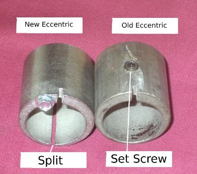
- eccentric old and new.jpg (35.2 KiB) Viewed 2562 times
.
Although not shown on the old Eccentric above many have a screw, like the new one, to help hold the position in the Headstock casting. On the newer Eccentric above notice the split is opposite the slot used to turn the Eccentric to adjust the upper Belt tension. If yours has the split (red arrow below) which should be able to be seen without removing the Idler Shaft Assembly you can realign the parts by un-clamping the Cap Screw (black Arrow) on the Headstock Casting, remove the two screws (blue and green arrows) and realign the Bearing and Eccentric even with the Headstock Casting. Re-clamp the Cap Screw and re-install the two screws. If the screw (green arrow) in the Eccentric no longer extends over the Bearing you may want to replace the screw with one that goes past the edge of the Bearing or add a washer to the existing screw. It is partly the clamping of the Cap Screw (black arrow) that holds the Idler Assembly and Eccentric in place. It is important not to over-tighten the Cap Screw to avoid breaking the Headstock Casting. The other two screws (blue and green arrows) also help keep the parts in the proper position.
_
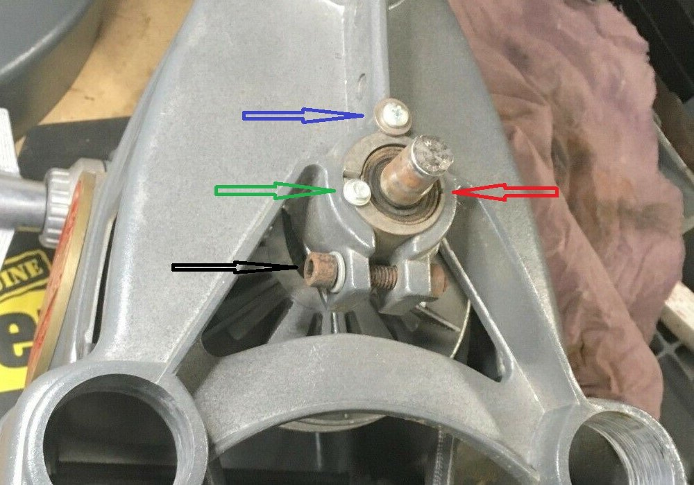
- Idler Shaft split eccentric arrows.jpg (124.8 KiB) Viewed 2562 times
 .
.