
Hi,
Today's project was to make a dust collection system for hand sanding and maybe to pick up some of the dust that gets away even when using your power sanders with dust collection.
If you recall this post:
https://forum.shopsmith.com/viewtopic.php?t=4313
"Ah but this box has a purpose, it was built to do something. In my files I have many many such projects and in fact this concept I am about to show you I must have about another 20 adaptations of."
This is another of those adaptations, so lets get to the pictures so you all know what I'm talking about.
[ATTACH]6497[/ATTACH]
[ATTACH]6498[/ATTACH]
[ATTACH]6499[/ATTACH]
[ATTACH]6500[/ATTACH]
[ATTACH]6501[/ATTACH]
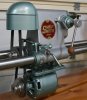
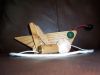
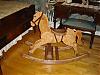
It was made from scrap material so appearance is on the lower end of shop grade, but fine for shop use. The "grip clips" that I used before are again the method of attachment to the machine. It is shown extended to one end but it could be placed any where along the machine. The dust hose collection point is simply a hole at this point but I my upgrade to something a bit better as time go along. I cut a piece away on one of the corners so I can lift it out and use either side of the peg board.
The top was going to be 1/8" peg board but I didn't have any in stock so I went with the 1/4". The bad news is I don't think this size is going to work. Testing showed a lot less performance then expected. I hope the smaller holes makes as much difference as needed. Keep in mind while it seems going from 1/4" holes to 1/8" seem like a minor change but IT is a big deal.
Ed
Today in my shop (sanding table)
Moderator: admin
Today in my shop (sanding table)
- Attachments
-
- DSCF7186rsc.jpg (51.78 KiB) Viewed 3745 times
-
- DSCF7187rsc.jpg (51.43 KiB) Viewed 3743 times
-
- DSCF7188sc.jpg (36.09 KiB) Viewed 3744 times
-
- DSCF7189sc.jpg (26.82 KiB) Viewed 3740 times
-
- DSCF7183sc.jpg (22.55 KiB) Viewed 3738 times
{Knight of the Shopsmith} [Hero's don't wear capes, they wear dog tags]
-
mickyd
- Platinum Member
- Posts: 2999
- Joined: Mon Feb 09, 2009 1:18 pm
- Location: San Diego, CA
- Contact:
Reducing down from 1/4" to 1/8" holes is a ~92% reduction in the combined area of the ~625 holes formed by the 25 x25 grid.reible wrote:Hi,
Today's project was to make a dust collection system for hand sanding........
The top was going to be 1/8" peg board but I didn't have any in stock so I went with the 1/4". The bad news is I don't think this size is going to work. Testing showed a lot less performance then expected. I hope the smaller holes makes as much difference as needed. Keep in mind while it seems going from 1/4" holes to 1/8" seem like a minor change but IT is a big deal.
Ed
625 1/4" holes = ~30 sq. in total
625 1/8" holes + ~7 sq. in total (update...I forgot to x by pi the first time:eek: .....hum.....pie.....I'm hungry!!)
This is an excellent concept for a sanding table. Keep us posted on your efforts.
Mike
Sunny San Diego
Sunny San Diego
The THICKNESS changed, not the hole size.
SS 500(09/1980), DC3300, jointer, bandsaw, belt sander, Strip Sander, drum sanders,molder, dado, biscuit joiner, universal lathe tool rest, Oneway talon chuck, router bits & chucks and a De Walt 735 planer,a #5,#6, block planes. ALL in a 100 square foot shop.
.
.
Bob
.
.
Bob
FYI
The total holes are 23 by 25 or 575 total.
Area of 1/4" holes 28.21 sq in.
Area of 1/8" holes 7.05 sq in.
Hose size (outside) 2-1/4".
Inside dimension guess 2-1/8"
Area of inside hose 3.54 sq in.
A couple of unknowns are how many of the holes will be covered by the work piece. And if the amount of air flow becomes to low it might require an adjustable intake vent... Got to keep the vacuum cleaner happy. Additional testing will give me a better idea of just how close to working this system is.
Ed
{Knight of the Shopsmith} [Hero's don't wear capes, they wear dog tags]
I'm separated from my woodworking library right now and can't look anything up, but I seem to remember that the box itself needs a sloped baffle in it. The baffle needs to start out high on the outside and terminate at your collection point.
In your case I'd cut four pieces of hardboard with angle cuts between the parallel edges. Put spacer blocks in where the parallel edges are and attach the hardboard.
The theory of the baffle is the farther away from the collection point you are the more air you have to move to collect. Suction is great right on top of the collection hose, but sucks ( sorry, couldn't resist ) or gradually degrades as you move toward the edge. Having a linear baffle reduces the amount of air you move as opposed to your current setup.
This may have gotten wordy, I apologize if I'm talking down to anyone.
I do have Sketchup with me. If you need further clarification give us your dimensions and I can draw up what I said.
In your case I'd cut four pieces of hardboard with angle cuts between the parallel edges. Put spacer blocks in where the parallel edges are and attach the hardboard.
The theory of the baffle is the farther away from the collection point you are the more air you have to move to collect. Suction is great right on top of the collection hose, but sucks ( sorry, couldn't resist
This may have gotten wordy, I apologize if I'm talking down to anyone.
I do have Sketchup with me. If you need further clarification give us your dimensions and I can draw up what I said.
Craig
Hartland, WI
-Mark 5 "Greenie" S/N 342238, Manuf. mmm/mmm 1957, Acq. Oct. 2008, Joiner S/N M067266
-10 E/ER(?) S/N Unknown, Joiner 4E S/N 40051
Hartland, WI
-Mark 5 "Greenie" S/N 342238, Manuf. mmm/mmm 1957, Acq. Oct. 2008, Joiner S/N M067266
-10 E/ER(?) S/N Unknown, Joiner 4E S/N 40051
-
tom_k/mo

- Platinum Member
- Posts: 856
- Joined: Mon Jul 14, 2008 3:58 pm
- Location: St. Louis, MO
- Contact:
Ed, nice idea. I made something similar to that years ago as a vacuum table for silk screen printing. One thing I noticed you might want to do... It looks as if your peg board is being supported by the rabbit joints on the edges only. You might want to put a couple 1-by supports in the middle areas of the box to support the middle, so that any downward pressure when sanding doesn't bow or crack the pegboard.
ShopSmith MarkV-520 with Belt Sander, Jointer, Band Saw, Strip Sander, Scroll Saw and Biscuit Jointer SPTs and a DC-3300...
Woodworking Hobbyist (Check out all my Woodworking Plans (http://vbwhiz.isa-geek.net/plans)
Aspiring Sandcarver: Breaking glass one grain at a time.
Black Powder Shooter (love the smell of burning sulfur).
Woodworking Hobbyist (Check out all my Woodworking Plans (http://vbwhiz.isa-geek.net/plans)
Aspiring Sandcarver: Breaking glass one grain at a time.
Black Powder Shooter (love the smell of burning sulfur).
Hi,
Yes I've seen plans like that but my model is a different way to look at it. My idea is that the workpiece will be over the middle area for the most part ie centered on the table. Looking at it this way all the center holes are blocked so the most "suction" will then be just to the outside of the work piece where I think I want it. Now it could be I'm wrong on this but it makes since to me.
And if I do need to add some angle pieces that would still make this a very simple project.
If it doesn't work at all then I can make it into a mini air hockey game by reconnecting it to the output port of the vacuum. Just four walls and two goals away.
Ed
etc92guy wrote:I'm separated from my woodworking library right now and can't look anything up, but I seem to remember that the box itself needs a sloped baffle in it. The baffle needs to start out high on the outside and terminate at your collection point.
In your case I'd cut four pieces of hardboard with angle cuts between the parallel edges. Put spacer blocks in where the parallel edges are and attach the hardboard.
The theory of the baffle is the farther away from the collection point you are the more air you have to move to collect. Suction is great right on top of the collection hose, but sucks ( sorry, couldn't resist
This may have gotten wordy, I apologize if I'm talking down to anyone.
I do have Sketchup with me. If you need further clarification give us your dimensions and I can draw up what I said.
{Knight of the Shopsmith} [Hero's don't wear capes, they wear dog tags]
Hi,
Yes you are correct about the peg board support. If I get it working well I had planned to add some dowels inside for added support. Maybe like 4 of them near the center... perhaps 3/4" dia. I was really not expecting it to be as stiff as it is, it takes some fair pressure to deform it but after some use that will likely not be the case.
Ed
tom_k/mo wrote:Ed, nice idea. I made something similar to that years ago as a vacuum table for silk screen printing. One thing I noticed you might want to do... It looks as if your peg board is being supported by the rabbit joints on the edges only. You might want to put a couple 1-by supports in the middle areas of the box to support the middle, so that any downward pressure when sanding doesn't bow or crack the pegboard.
{Knight of the Shopsmith} [Hero's don't wear capes, they wear dog tags]
Ed:
Thanks for posting. One of my "projects to do" is just such a sanding table but I hadn't thought of making it to fit on the SS. Great idea.
I know this would reduce the airflow more, but I was also thinking of covering the pegboard with a router mat, one with holes in it, to prevent slipage of the workpiece.
Someday.
John