So maybe that's why there are no details?

Forum for Maintenance and Repair topics. Feel free to ask questions or contribute.

Moderator: admin

User avatar
mgdesigns
Gold Member
Posts: 259
Joined: Tue Jul 20, 2010 12:04 pm
Location: Brentwood, TN
Contact:

So maybe that's why there are no details?

Post by mgdesigns »

So maybe that's why there are no details? - Curious? :rolleyes: I was, so I removed the retaining ring from the back side of the driven gear on the top shaft. BOING - :mad: that holds the retainer that the big compression spring pushes against.

So, I disassembled the the whole assemble, which I guessed was a torque limiting clutch for the Gilson Drive Gear. Wow, I cleaned it all up being careful not to break any of the fiber board gears, or damaging with solvents. I got it all back together, but spent 2.5 hours trying to figure out how to compress the spring and get the retaining ring to snap back into the groove. I had just about given up, after using a neighbor's drill press, and a long impact socket as a ram.

Then I tried to use c-clamps - no good.
Then my engraver's vise - no good - too long of a spread.
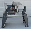
Then it dawned on me. :rolleyes: I had just received the 1950's Magna Jointer and support tubes - VOILA!
I used one of the tubes as a ram, and the quill on the SS to press the whole mess back together. After a couple of tries and finally got the snap ring into the groove. I hope it stays. I might go by TSC (Tractor Supply Co.) and see if they have a new one - now that I have the technique to press it together figured out.;)
User avatar
billmayo
Platinum Member
Posts: 2342
Joined: Fri Jul 21, 2006 3:31 pm
Location: Plant City, FL

Gilmer Clutch Information

Post by billmayo »

I have dozens of pictures and files on rebuilding and testing the Gilmer clutch. I offer rebuilding service, exchange or rebuilt units. I have dozens of the clutches and all related parts available. Please contact me for additional infomation. Thanks.
Bill Mayo bill.mayo@verizon.net
Shopsmith owner since 73. Sell, repair and rebuild Shopsmith, Total Shop & Wood Master headstocks, SPTs, attachments, accessories and parts. US Navy 1955-1975 (FTCS/E-8)
User avatar
mgdesigns
Gold Member
Posts: 259
Joined: Tue Jul 20, 2010 12:04 pm
Location: Brentwood, TN
Contact:

Post by mgdesigns »

What size retaining clip is the one I've been trying to get to stay in the groove?
User avatar
mgdesigns
Gold Member
Posts: 259
Joined: Tue Jul 20, 2010 12:04 pm
Location: Brentwood, TN
Contact:

Key for keyway in Control Pulley?

Post by mgdesigns »

Key for keyway in Control Pulley?

OK - I am re-assembling the Headstock assembly - I have everything prepped and I noticed there's a keyway in the Control Pulley, but on the Exploded parts drawing there is no key designation. I believe you'd have to have a key to alignment between the the 2 halves of the pulley assembly, and I have key stock material enough to make it but don't know exactly how long to cut it. HELP, Please. Thank you.

Here's the exploded view:
http://www.shopsmith.com/ownersite/part ... xpview.htm
Ron309753
Gold Member
Posts: 355
Joined: Tue Jul 01, 2008 10:25 pm
Location: Marengo, OH

Post by Ron309753 »

The key is part #108 in the diagram. It should have been on the idler shaft when you disassembed it. The key not only aligns the idler sheave and control sheave, but without the key the sheaves would just spin on the shaft. The key should run the length of the keyway from the retaining ring to the end of the idler shaft.

There should also have been an idler sheave clip (part #107). It is a u shaped piece of wire with squared corners. It, along with the retaining ring, keeps the idler sheave from moving back and forth on the idler shaft.

First slide the idler sheave onto the shaft and over the key until it rests against the retaining ring. Then slide the clip onto the shaft until it engages the groove in the shaft. Then just slide on the control sheave.

Hope this helps!

Sincerely,

Ron309753
User avatar
mgdesigns
Gold Member
Posts: 259
Joined: Tue Jul 20, 2010 12:04 pm
Location: Brentwood, TN
Contact:

Post by mgdesigns »

I got too anxious, because I need to get this Shopsmith working by tomorrow, so I called Shopsmith Customer service. I spoke to Linda (very knowledgeable and very helpful), and she explained how to disassemble the whole shaft. I did it (except I left the bearing on -it spins fine) and I made a hooked ended key the length of the shaft. I broke a $30 pair of jeweler's ring bender pliers trying to get the hook on the end (oh well) - I can probably use a friend's laser welder to fix those.

I got the new key the keyway and the pulley slid right on. I finished the whole assembly of the headstock and removed all of the white lithium grease I had placed on the normal oiled points, and I oiled. I set it to slowest speed, and the v-pulley looks very slack, so I'll wait until later to fire it up. The pulley is a genuine Shopsmith-Pirelli, and looks OK but should probably be replaced.

Now all that's left to do is plug it into power. I'll wait until tomorrow to do that. Got a wood turner's meeting to go to and soccer practice for the kids.
judaspre1982
Platinum Member
Posts: 1237
Joined: Tue Jul 08, 2008 10:10 pm

Post by judaspre1982 »

===========================
Attachments
Picture 041.jpg
Picture 041.jpg (117.87 KiB) Viewed 3715 times
Picture 042.jpg
Picture 042.jpg (110.74 KiB) Viewed 3716 times
Picture 044.jpg
Picture 044.jpg (139.82 KiB) Viewed 3717 times
Last edited by judaspre1982 on Thu May 11, 2017 1:02 pm, edited 1 time in total.
judaspre1982
Platinum Member
Posts: 1237
Joined: Tue Jul 08, 2008 10:10 pm

Post by judaspre1982 »

=================================
Attachments
Picture 046.jpg
Picture 046.jpg (135.73 KiB) Viewed 3720 times
Last edited by judaspre1982 on Thu May 11, 2017 12:59 pm, edited 1 time in total.
User avatar
JPG
Platinum Member
Posts: 35600
Joined: Wed Dec 10, 2008 7:42 pm
Location: Lexington, Ky (TAMECAT territory)

Post by JPG »

Not sure of the Greenie vintage, but later mark 5/V have a counter bore hole at the end of the keyway under the front edge of the idler sheave. The key has a crook in the end that slips down into that bore. When the idler sheave is installed on the shaft, that crook in the bore prevents the key from slipping along the length of the shaft.
╔═══╗
╟JPG ╢
╚═══╝

Goldie(Bought New SN 377425)/4" jointer/6" beltsander/12" planer/stripsander/bandsaw/powerstation /Scroll saw/Jig saw /Craftsman 10" ras/Craftsman 6" thicknessplaner/ Dayton10"tablesaw(restoredfromneighborstrashpile)/ Mark VII restoration in 'progress'/ 10
E[/size](SN E3779) restoration in progress, a 510 on the back burner and a growing pile of items to be eventually returned to useful life. - aka Red Grange
judaspre1982
Platinum Member
Posts: 1237
Joined: Tue Jul 08, 2008 10:10 pm

Post by judaspre1982 »

==================================
Attachments
Picture 047.jpg
Picture 047.jpg (131.07 KiB) Viewed 3699 times
Picture 048.jpg
Picture 048.jpg (118.49 KiB) Viewed 3699 times
Last edited by judaspre1982 on Thu May 11, 2017 1:01 pm, edited 1 time in total.
Post Reply