I am new to ss. when I turn my speed dial after I turn the machine on the speed indicator plate does not turn with the dial. does it suppose to or not. if it should turn how do i fix it?
Terrell0214
speed dial question
Moderator: admin
-
dusty

- Platinum Member
- Posts: 21530
- Joined: Wed Nov 22, 2006 6:52 am
- Location: Tucson (Wildcat Country), Arizona
Yes, the dial should go up and down as you change speeds. This dial is the visual indicator of the speed you have chosen.terrell0214 wrote:I am new to ss. when I turn my speed dial after I turn the machine on the speed indicator plate does not turn with the dial. does it suppose to or not. if it should turn how do i fix it?
Terrell0214
WARNING: Do not turn the speed dial except when the Mark V is running. Damage will likely be done if you do. An exception to this warning will be mentioned if you view the Sawdust Session referenced in the next paragraph.
View the following Sawdust Session and I believe your questions about the Speed Settings will all be answered. If not, please come back for more help.
"Making Sawdust Safely"
Dusty
Sent from my Dell XPS using Firefox.
Dusty
Sent from my Dell XPS using Firefox.

Terrell
Happened to me the other day while doing a high speed adjustment to my machine. I turned the speed control handle, the machine increased in speed but the dial did not move.
Upon inspection, I realized I did not get the allen screw in the hole on the shaft, but I tightened the screw enough that me control increased the speed.
Take your control handle off, make sure the gear on the handle goes all the way into the larger gear off of the dial, then try again.
Give this a try, best of luck.
Happened to me the other day while doing a high speed adjustment to my machine. I turned the speed control handle, the machine increased in speed but the dial did not move.
Upon inspection, I realized I did not get the allen screw in the hole on the shaft, but I tightened the screw enough that me control increased the speed.
Take your control handle off, make sure the gear on the handle goes all the way into the larger gear off of the dial, then try again.
Give this a try, best of luck.
Jerry Torok
Spring, TX
Shopsmith PowerPro 520 with Bandsaw, Jointer, Jigsaw, Belt Sander, Pro-planer, Incra 120 Miter Gauge & Incra Miter Express, Incra Twin-Linear
Spring, TX
Shopsmith PowerPro 520 with Bandsaw, Jointer, Jigsaw, Belt Sander, Pro-planer, Incra 120 Miter Gauge & Incra Miter Express, Incra Twin-Linear
-
mickyd
- Platinum Member
- Posts: 2999
- Joined: Mon Feb 09, 2009 1:18 pm
- Location: San Diego, CA
- Contact:
I too had the same issue last night.....set screw wasn't secure in the shaft hole. As I fixed it, I questioned what tip the set screw was supposed to have. Normally, a set screw that engages into a hole similar to the one on the shaft will be a cone point (semi-pointy). My set screw is a cup point (concave dish) and the point diameter is almost the same size as the OD of the shaft hole. So my question is......jctorok wrote:Terrell
Happened to me the other day while doing a high speed adjustment to my machine. I turned the speed control handle, the machine increased in speed but the dial did not move.
Upon inspection, I realized I did not get the allen screw in the hole on the shaft, but I tightened the screw enough that me control increased the speed.
Take your control handle off, make sure the gear on the handle goes all the way into the larger gear off of the dial, then try again.
Give this a try, best of luck.
What is the correct set screw point for this application? Do I have a cup point in error?
Mike
Sunny San Diego
Sunny San Diego
-
JPG

- Platinum Member
- Posts: 35600
- Joined: Wed Dec 10, 2008 7:42 pm
- Location: Lexington, Ky (TAMECAT territory)
mickyd wrote:I too had the same issue last night.....set screw wasn't secure in the shaft hole. As I fixed it, I questioned what tip the set screw was supposed to have. Normally, a set screw that engages into a hole similar to the one on the shaft will be a cone point (semi-pointy). My set screw is a cup point (concave dish) and the point diameter is almost the same size as the OD of the shaft hole. So my question is......
What is the correct set screw point for this application? Do I have a cup point in error?
I vote for 'semi-pointy'. Make sure it ONLY contacts the shaft inside the 'hole'!:eek: Actually either is adequate IF installed properly!;)
P.S. Take good care of that shaft. It can get boogered up far too easily and lead to 'wobbly' shaft problems.
╔═══╗
╟JPG ╢
╚═══╝
Goldie(Bought New SN 377425)/4" jointer/6" beltsander/12" planer/stripsander/bandsaw/powerstation /Scroll saw/Jig saw /Craftsman 10" ras/Craftsman 6" thicknessplaner/ Dayton10"tablesaw(restoredfromneighborstrashpile)/ Mark VII restoration in 'progress'/ 10E[/size](SN E3779) restoration in progress, a 510 on the back burner and a growing pile of items to be eventually returned to useful life. - aka Red Grange
╟JPG ╢
╚═══╝
Goldie(Bought New SN 377425)/4" jointer/6" beltsander/12" planer/stripsander/bandsaw/powerstation /Scroll saw/Jig saw /Craftsman 10" ras/Craftsman 6" thicknessplaner/ Dayton10"tablesaw(restoredfromneighborstrashpile)/ Mark VII restoration in 'progress'/ 10E[/size](SN E3779) restoration in progress, a 510 on the back burner and a growing pile of items to be eventually returned to useful life. - aka Red Grange
-
mickyd
- Platinum Member
- Posts: 2999
- Joined: Mon Feb 09, 2009 1:18 pm
- Location: San Diego, CA
- Contact:
[quote="JPG40504"]I vote for 'semi-pointy'. Make sure it ONLY contacts the shaft inside the 'hole'!:eek: Actually either is adequate IF installed properly!]
I still wonder what was the 'original' set screw point style out of the factory was?? I would think SS would have put a flat on the shaft vs. a tapered hole has they planned on a cup point.
I am going to install the cone point. The nice thing about that is when installing, you first lightly tighten the set screw to contact the shaft then while still applying a little torque to the set screw, push the dial on and you will feel the point drop off and go into the hole. At that point, you should then be able to rotate a set screw several more turns ensuring adequate recess into the hole and bottom out contact.
I still wonder what was the 'original' set screw point style out of the factory was?? I would think SS would have put a flat on the shaft vs. a tapered hole has they planned on a cup point.
I am going to install the cone point. The nice thing about that is when installing, you first lightly tighten the set screw to contact the shaft then while still applying a little torque to the set screw, push the dial on and you will feel the point drop off and go into the hole. At that point, you should then be able to rotate a set screw several more turns ensuring adequate recess into the hole and bottom out contact.
Mike
Sunny San Diego
Sunny San Diego
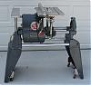
Speed Control Handle Set Screw
[quote="mickyd"]I still wonder what was the 'original' set screw point style out of the factory was?? I would think SS would have put a flat on the shaft vs. a tapered hole has they planned on a cup point. QUOTE]
Yes, I have a few worm gear shafts with a machined flat slot. I replace the cup set screw in the speed control handle with a new Knurled Cup set screw,. I find I have to remove the worm gear shaft, check that the worm gear part of the shaft is not bent (around 10% are bent) and file the shaft until the speed control handle fits snug.
Yes, I have a few worm gear shafts with a machined flat slot. I replace the cup set screw in the speed control handle with a new Knurled Cup set screw,. I find I have to remove the worm gear shaft, check that the worm gear part of the shaft is not bent (around 10% are bent) and file the shaft until the speed control handle fits snug.
Bill Mayo bill.mayo@verizon.net
Shopsmith owner since 73. Sell, repair and rebuild Shopsmith, Total Shop & Wood Master headstocks, SPTs, attachments, accessories and parts. US Navy 1955-1975 (FTCS/E-8)
Shopsmith owner since 73. Sell, repair and rebuild Shopsmith, Total Shop & Wood Master headstocks, SPTs, attachments, accessories and parts. US Navy 1955-1975 (FTCS/E-8)
-
mickyd
- Platinum Member
- Posts: 2999
- Joined: Mon Feb 09, 2009 1:18 pm
- Location: San Diego, CA
- Contact:
billmayo wrote: Yes, I have a few worm gear shafts with a machined flat slot. I replace the cup set screw in the speed control handle with a new Knurled Cup set screw,. I find I have to remove the worm gear shaft, check that the worm gear part of the shaft is not bent (around 10% are bent) and file the shaft until the speed control handle fits snug.
What causes the shafts to bend? Is it that the dial isn't fully on giving giving more of a 'bending' mechanical advantage when turning the dial?
Mike
Sunny San Diego
Sunny San Diego
The worm gear rides up on the side pf the quadrant teeth and will bend the worm gear shaft when forced to do this action. Otherwise the Speed Control handle set screw will badly scored the worm gear shaft if the worm gear is jammed on the top of the quadrant teeth. The only time this occurs is when the quadrant teeth have been badly worn on one side or broken on that side. This also bends the leg on the backet holding the quadrant allowing the quadrant teeth to wear on the outer edge.mickyd wrote:billmayo wrote: What causes the shafts to bend? Is it that the dial isn't fully on giving giving more of a 'bending' mechanical advantage when turning the dial?
I have been replacing the quadrant roll pin with a #10-32 X 2 1/2" allen head bolt, 2 star washers and a thin Nylock nut after straightening the bracket legs. I have a computer file and pictures plus these parts (free) for this change if anyone is interested. I have been doing this change for around 6 years and over 75 Speed Control Assemblies without any returns or futher quadrant damage at this time.
I have a lengthly soapbox discussion available as to why this occurs but I find just fixing the problem is quicker and my opinion is best saved for another day and subject.
Bill Mayo bill.mayo@verizon.net
Shopsmith owner since 73. Sell, repair and rebuild Shopsmith, Total Shop & Wood Master headstocks, SPTs, attachments, accessories and parts. US Navy 1955-1975 (FTCS/E-8)
Shopsmith owner since 73. Sell, repair and rebuild Shopsmith, Total Shop & Wood Master headstocks, SPTs, attachments, accessories and parts. US Navy 1955-1975 (FTCS/E-8)