Page 1 of 2
disassembled humming motor - resistance checks?
Posted: Fri Feb 18, 2011 7:07 pm
by damagi
I have a newer motor that is humming. No evidence of burning. One of the leads into the motor had lots of cracking, so I stripped off the old insulation and heatshrinked the wire. Since I have the coil portion seperated out, what are the appropriate resistance checks to ensure everything is functioning?
Also, since I am this far, if someone has details on adding a reversing switch to this GE 1 1/8 HP motor that would be great.
Posted: Fri Feb 18, 2011 7:15 pm
by JPG
damagi wrote:I have a newer motor that is humming. No evidence of burning. One of the leads into the motor had lots of cracking, so I stripped off the old insulation and heatshrinked the wire. Since I have the coil portion seperated out, what are the appropriate resistance checks to ensure everything is functioning?
Also, since I am this far, if someone has details on adding a reversing switch to this GE 1 1/8 HP motor that would be great.
Send this as a PM to Bill Mayo!!!!!!!!!!! or e-mail him - check his signature line.
Posted: Fri Feb 18, 2011 7:18 pm
by damagi
JPG40504 wrote:Send this as a PM to Bill Mayo!!!!!!!!!!! or e-mail him - check his signature line.
I have some notes he sent me a while back...printed them out and have been studying them. I'm a little groggy, so maybe thats preventing me from fully understanding them

Posted: Sat Feb 19, 2011 2:50 am
by dusty
damagi wrote:I have some notes he sent me a while back...printed them out and have been studying them. I'm a little groggy, so maybe thats preventing me from fully understanding them
Email him and ask for his number. Then call him. He'll help you - no doubt.
Shopsmith Motors
Posted: Sat Feb 19, 2011 6:31 am
by billmayo
JPG40504 wrote:Send this as a PM to Bill Mayo!!!!!!!!!!! or e-mail him - check his signature line.
You need a real sensitive OHM meter (+-.1 ohm). Between the black/blue wire and the white wire (1-2 ohms), between the red wire and white wire (4-5 ohms). Be sure to measure between each wire and the the case that there is no connection/short. Shopsmith motors will operate with any of the coil wires shorted to the case without a ground connection at the plug. This is a common problem I find on overheated motors. Makes for a hair raising experience.
All the string wrapping should be intact (not burnt or broken) with no black or burned coil wires or insulation (all coil wires should show the same coloring on each end of the casing).
I can add the reversing capability to the GE and AO Smith 3/4 & 1 1/8 HP motors, not the Emerson motors(wire connections are hidden). Contact me for pictures and questions.
Thanks.
Bill Mayo
http://www.billstoolz.com
Email:
annbill.mayo@comcast.net
813-764-8343 (after 10:00am and before 10:00pm EDT)
William Mayo
Bill’s Toolz
3031 Turkey Creek Road
Plant City, FL 33566
Posted: Sun Feb 20, 2011 10:44 am
by damagi
Ok, so I went through and did some checks. I have a white and blue wire that are bonded together, a black wire, and a red wire. I also checked the case to each. Readings using my craftsman pro digital multimeter are as follows:
Code: Select all
	White/Blue	Red	Black	Ground
White/Blue	0	6.5	0.4	NC
Red	6.5	0	6	NC
Black	0.4	6	0	NC
Ground	NC	NC	NC	0
My multimeter's cap tester was reading 0uF on the cap...but I need to find another cap to test against to be sure its reading correctly. The contact points on the switch look pristine.
I'm starting to suspect the cap since the motor looks basically mint otherwise.
Motor Hums
Posted: Sun Feb 20, 2011 12:00 pm
by billmayo
When the motor hums, it is normally the start circuit being open. I have found only one seized bearing to prevent a motor from starting. All your readings looks good.
I remove the 2 red wires from the capacitor and check the ohms between each red capacitor wire and the power input wires.
Depending on the motor manufacture, one end of the start windings are connected to the black or blue input wire or to the white input wire (4-5 ohms). The other red capacitor wire will directly to the centrifugal switch or start relay and to the other input power wire. It should read 0 ohms if the switch or relay is good. I have not found a bad capacitor in any Shopsmith motor at this time.
Posted: Sun Feb 20, 2011 12:02 pm
by damagi
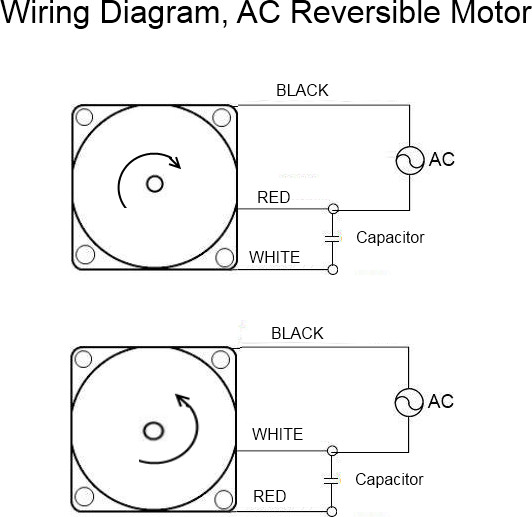
btw, Is this diagram reasonably accurate?
Posted: Sun Feb 20, 2011 6:14 pm
by billmayo
damagi wrote:
btw, Is this diagram reasonably accurate?
Yes, switching the wires to each end of the start windings is what changes the rotation. I connect the start winding wires to the center position of a DPDT toggle switch and add an addition wire to each of the power input wires to one end of the DPDT switch and reverse the wires to the other end of the DPDT switch. This is a diagram that someone posted on one of the Forums.
[ATTACH]11996[/ATTACH]
Posted: Mon Feb 21, 2011 1:53 pm
by damagi
Some shots of the motor. The bare wire was previously white. The insulation was cracked, so I removed all of it.
[ATTACH]11999[/ATTACH]
[ATTACH]12000[/ATTACH]
[ATTACH]12001[/ATTACH]