I recently refurbished a Mark V mount planer. To synchronize the table, I used a dial indicator and got all four posts to within 0.002" to the tie bars.
Since I installed new knives, I simply bottomed out the leveling screws and set the knives (per PTWFE). A test cut gave a difference of 0.004" across a 10" board. Definitely acceptable.
My problem is that I watched Nick's sawdust session about setting the planer knives using a dial indicator. In that video, the cutterhead was true to the table. In my case the cutterhead is off by 0.010", but the tie bars are true (to within 0.002"). I know 0.010" is probably nothing to worry about, but if the tie bars are true why isn't the cutterhead? Could I have missed something in rebuilding the planer?
Any help is greatly appreciated.
Planer Issues
Moderator: admin
-
michaeltoc
- Gold Member
- Posts: 222
- Joined: Wed Feb 25, 2009 9:51 pm
- Location: White Plains, NY
Planer Issues
Michael
Mark V Model 500 (1985) upgraded to 520 (2009) and PowerPro (2011); Bandsaw, Jointer, Jigsaw, Planer.
Mark V Model 500 (1985) upgraded to 520 (2009) and PowerPro (2011); Bandsaw, Jointer, Jigsaw, Planer.
-
JPG

- Platinum Member
- Posts: 35600
- Joined: Wed Dec 10, 2008 7:42 pm
- Location: Lexington, Ky (TAMECAT territory)
michaeltoc wrote:I recently refurbished a Mark V mount planer. To synchronize the table, I used a dial indicator and got all four posts to within 0.002" to the tie bars.
Since I installed new knives, I simply bottomed out the leveling screws and set the knives (per PTWFE). A test cut gave a difference of 0.004" across a 10" board. Definitely acceptable.
My problem is that I watched Nick's sawdust session about setting the planer knives using a dial indicator. In that video, the cutterhead was true to the table. In my case the cutterhead is off by 0.010", but the tie bars are true (to within 0.002"). I know 0.010" is probably nothing to worry about, but if the tie bars are true why isn't the cutterhead? Could I have missed something in rebuilding the planer?
Any help is greatly appreciated.
How are you determining that?
This seems on the surface as being contradictory.
╔═══╗
╟JPG ╢
╚═══╝
Goldie(Bought New SN 377425)/4" jointer/6" beltsander/12" planer/stripsander/bandsaw/powerstation /Scroll saw/Jig saw /Craftsman 10" ras/Craftsman 6" thicknessplaner/ Dayton10"tablesaw(restoredfromneighborstrashpile)/ Mark VII restoration in 'progress'/ 10E[/size](SN E3779) restoration in progress, a 510 on the back burner and a growing pile of items to be eventually returned to useful life. - aka Red Grange
╟JPG ╢
╚═══╝
Goldie(Bought New SN 377425)/4" jointer/6" beltsander/12" planer/stripsander/bandsaw/powerstation /Scroll saw/Jig saw /Craftsman 10" ras/Craftsman 6" thicknessplaner/ Dayton10"tablesaw(restoredfromneighborstrashpile)/ Mark VII restoration in 'progress'/ 10E[/size](SN E3779) restoration in progress, a 510 on the back burner and a growing pile of items to be eventually returned to useful life. - aka Red Grange
-
michaeltoc
- Gold Member
- Posts: 222
- Joined: Wed Feb 25, 2009 9:51 pm
- Location: White Plains, NY
I used a dial indicator on the center of the cutterhead (as Nick did in the video). From one end to the other there is a difference of 0.010".JPG40504 wrote:How are you determining that?
This seems on the surface as being contradictory.
Michael
Mark V Model 500 (1985) upgraded to 520 (2009) and PowerPro (2011); Bandsaw, Jointer, Jigsaw, Planer.
Mark V Model 500 (1985) upgraded to 520 (2009) and PowerPro (2011); Bandsaw, Jointer, Jigsaw, Planer.
I would think that the key dimension is from the table to the cutter head. If you look at this picture from the Shopsmith website -- http://www.shopsmith.com/ownersite/cata ... head-1.jpg -- it shows a set-up for adjusting the cutter blades with the cutter head removed from the planer. The only way this works is if the table is perpendicular with the cutter head because the only reference point you have at this stage while adjusting the cutters is the cutter head itself. That said, if you're getting a flat board within .004" across a 10" board, I wouldn't worry too much about the cutter head alignment with the table.
Art in Western Pennsylvania
-
dusty

- Platinum Member
- Posts: 21530
- Joined: Wed Nov 22, 2006 6:52 am
- Location: Tucson (Wildcat Country), Arizona
pennview wrote:I would think that the key dimension is from the table to the cutter head. If you look at this picture from the Shopsmith website -- http://www.shopsmith.com/ownersite/catalog/images/cr_cutterhead-1.jpg -- it shows a set-up for adjusting the cutter blades with the cutter head removed from the planer. The only way this works is if the table is perpendicular with the cutter head because the only reference point you have at this stage while adjusting the cutters is the cutter head itself. That said, if you're getting a flat board within .004" across a 10" board, I wouldn't worry too much about the cutter head alignment with the table.
That jig would be simple to build and easy to use but all that it provides in the end is three cutter bars that are all the same depth across the entire bar and from bar to bar.
Exactly the same thing can be done with the cutter head in the planer. Probably takes longer but who is "on the clock" when in the shop?
BTW Isn't the "final critical dimension" the distance from the planer table surface to the cutting edge of the cutter bar with the inherent requirement that they all be "exactly" the same?
"Making Sawdust Safely"
Dusty
Sent from my Dell XPS using Firefox.
Dusty
Sent from my Dell XPS using Firefox.
-
michaeltoc
- Gold Member
- Posts: 222
- Joined: Wed Feb 25, 2009 9:51 pm
- Location: White Plains, NY
Yes - I agree, but I am a precision junkie (hazard of being an engineer). However, because it was easy to get the tie bars aligned without much fiddling, I feel that I should be able to get the cutterhead aligned to within the same tolerance.pennview wrote:That said, if you're getting a flat board within .004" across a 10" board, I wouldn't worry too much about the cutter head alignment with the table.
The tie bars are attached to two identical side castings, but the cutterhead is attached to the side castings by means of two bearing support castings. I guess I need to see if I can shim/tweak the bearing supports to true up the cutterhead.
Michael
Mark V Model 500 (1985) upgraded to 520 (2009) and PowerPro (2011); Bandsaw, Jointer, Jigsaw, Planer.
Mark V Model 500 (1985) upgraded to 520 (2009) and PowerPro (2011); Bandsaw, Jointer, Jigsaw, Planer.
-
JPG
- Platinum Member
- Posts: 35600
- Joined: Wed Dec 10, 2008 7:42 pm
- Location: Lexington, Ky (TAMECAT territory)
Realize the setting of the table(chain sprocket syncing) is done relative to the tie bars merely as a matter of convenience for those not having a dial indicator etc.
I suggest repeating that table height adjustment, but use the dial indicator etc. and reference(vertical) to the cutter head rather than the tie bars.
I would not be surprised to find several thousands slop in the tie rod mounting location.
I suggest repeating that table height adjustment, but use the dial indicator etc. and reference(vertical) to the cutter head rather than the tie bars.
I would not be surprised to find several thousands slop in the tie rod mounting location.
╔═══╗
╟JPG ╢
╚═══╝
Goldie(Bought New SN 377425)/4" jointer/6" beltsander/12" planer/stripsander/bandsaw/powerstation /Scroll saw/Jig saw /Craftsman 10" ras/Craftsman 6" thicknessplaner/ Dayton10"tablesaw(restoredfromneighborstrashpile)/ Mark VII restoration in 'progress'/ 10E[/size](SN E3779) restoration in progress, a 510 on the back burner and a growing pile of items to be eventually returned to useful life. - aka Red Grange
╟JPG ╢
╚═══╝
Goldie(Bought New SN 377425)/4" jointer/6" beltsander/12" planer/stripsander/bandsaw/powerstation /Scroll saw/Jig saw /Craftsman 10" ras/Craftsman 6" thicknessplaner/ Dayton10"tablesaw(restoredfromneighborstrashpile)/ Mark VII restoration in 'progress'/ 10E[/size](SN E3779) restoration in progress, a 510 on the back burner and a growing pile of items to be eventually returned to useful life. - aka Red Grange
-
michaeltoc
- Gold Member
- Posts: 222
- Joined: Wed Feb 25, 2009 9:51 pm
- Location: White Plains, NY
Great idea! I will try that.JPG40504 wrote:Realize the setting of the table(chain sprocket syncing) is done relative to the tie bars merely as a matter of convenience for those not having a dial indicator etc.
I suggest repeating that table height adjustment, but use the dial indicator etc. and reference(vertical) to the cutter head rather than the tie bars.
I would not be surprised to find several thousands slop in the tie rod mounting location.
Michael
Mark V Model 500 (1985) upgraded to 520 (2009) and PowerPro (2011); Bandsaw, Jointer, Jigsaw, Planer.
Mark V Model 500 (1985) upgraded to 520 (2009) and PowerPro (2011); Bandsaw, Jointer, Jigsaw, Planer.

Planer Adjustments
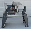
Moving the jack shaft sprocket one (1) tooth on the synchronizing chain moves the table height .004”. I use the front right tie bar as my reference point for checking with the other three (3) measurement points (left front, right rear, left rear) with the tie bars. I move the chain at least 2 teeth at the other 3 jack shaft sprockets before starting these measurements. Using a feeler gauge with a 3” engine intake valve, I determine each of the 3 differences from the starting reference point. I note the feeler gauge differences and then move the chain for one (1) jack shaft sprocket tooth for each .004” difference at each of the 3 other measurement points.. Retension the chain and check again. I forgot if right or left rotation is needed for the sprockets at this time. Very quick to check.
I set all 3 cutter head knives with the front tie bar using the knife setting gauge that was supplied with the planer. I plane a 2” X 10“ X 2‘-3‘ board to measure to insure my adjustment is OK.
Bill
I set all 3 cutter head knives with the front tie bar using the knife setting gauge that was supplied with the planer. I plane a 2” X 10“ X 2‘-3‘ board to measure to insure my adjustment is OK.
Bill
Bill Mayo bill.mayo@verizon.net
Shopsmith owner since 73. Sell, repair and rebuild Shopsmith, Total Shop & Wood Master headstocks, SPTs, attachments, accessories and parts. US Navy 1955-1975 (FTCS/E-8)
Shopsmith owner since 73. Sell, repair and rebuild Shopsmith, Total Shop & Wood Master headstocks, SPTs, attachments, accessories and parts. US Navy 1955-1975 (FTCS/E-8)