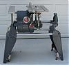
Modifying/Upgrading a 1955 Greenie

Forum for Maintenance and Repair topics. Feel free to ask questions or contribute.

Moderator: admin

User avatar
Culprit
Gold Member
Posts: 234
Joined: Sun Dec 04, 2011 12:37 am
Location: Virginia

Modifying/Upgrading a 1955 Greenie

Post by Culprit »

When I was given a 1955 Greenie a few weeks ago. I cleaned it up cosmetically, oiled the basic spots, and went to work learning to use it. I ended up breaking the gilmer belt within an hour. I'm sure it was weak from dry rot since the machine had sat for so long.

Now that I've taken things apart to change the belt, I'm letting this snowball pick up speed. I am going to replace the roll pin that the quadrant pivots on - if I can ever find a size 10 bolt with 1 1/8 - 1 3/8ths unthreaded length. I may have to order one online from Grainger or something.

I would like to add a switch to reverse the motor. From what I've read on this forum in the past two weeks since becoming a Shopsmith owner, Bill Mayo is the man to talk to. Bill... I have a 3/4 hp A. O. Smith motor from 1955. I'm not afraid to open it up and find the right leads to wire to the switch that will allow me to reverse the starting windings. I read some old posts of yours where you said that sometimes it works and sometimes it doesn't on some of the older motors. Can you explain in more detail why - what is different from motor to motor, and what exactly do I need to look for when I open it up. I'm assuming I'll have to take the nut and spring and sheeves off to get the motor spindle out the other end to take it apart. How did you run the leads out of the motor to the switch? Any words of wisdom here would be greatly appreciated.

I also want to cut an access hole in the back side of the headstock. What diameter hole have most people found to work the best. Also, how do you guys re-mount the Shopsmith emblem so that you can remove it to access the access hole without dropping the motor to get the little friction-fit tabs off the posts that hold the emblem on?

The next thing I'm considering is adding another quill bearing or two. I saw on older posts that Holsgo went to three - I would like to know where you sent the quill to have it machined, or if you did it yourself.

From searching old posts here on the forum, most people seem to stack an extra bearing or two at the end of the quill next to the existing bearing. I found this old magazine clipping that adds an extra bearing on the other end of the quill. It makes a lot of sense to me to support the quill from both ends instead of just stacking bearings next to each other - but there must be a reason that more people don't do it that way (or maybe they do and I just don't know it yet). Have any of you tried the method in this magazine clipping? Can anyone tell me the pros and cons of it?

Image

Next up: holes for oiling the sheaves - my 1955 Greenie doesn't have them. What size hole is best (what size hole did the factory use in those fancy modern 1960's machines)?

Added weight: I'm going to build a shelf between the legs, but I also like Holsgo's approach to adding vinyl sleeves of sand inside the bench tubes and ways. There is a reason that hollow drive shafts are filled with sand in machinery designed for quiet operation - in addition to the extra weight, it dampens vibrations quite a bit. Holsgo - where did you find the vinyl sleeves to use?

Are there any other modifications/upgrades I should consider while I'm at it? I have decided to stick with the gilmer drive - I've spent enough money already buying a chuck, live center, power couplers, etc. I'm also going to stick with the old 3/4's hp motor for the same reason.

Thanks again for all the help folks on this forum have been to me already.

User avatar
holsgo
Platinum Member
Posts: 740
Joined: Sat Jul 04, 2009 9:48 pm
Location: Manassas, VA

Post by holsgo »

You have quite a list of things to do. Bill is really the man on the reversing switch and I haven't tried it yet.
As far as the bearings, it's simply easier access that allows you to stack bearings behind the existing. To try and go on the other end is an issue of getting a bearing with a smaller inner race over the splines to mount on the shaft. There would be machining inside the quill as well. I gave a rundown of how I did it in another thread I think. My approach took quite some time but I did get it done. Now that I've started an apprenticeship at a machine shop I see all of the other ways.
The sleeves for the sand are vinyl left over for a project from work. I simply made sleeves and used contact cement to make them. Sealed the ends with gorilla tape so they could be emptied without taking the machine apart.
User avatar
holsgo
Platinum Member
Posts: 740
Joined: Sat Jul 04, 2009 9:48 pm
Location: Manassas, VA

Post by holsgo »

I cut a 3 inch hole and used rubber grommets in the fang like projections to create a friction fit for the prongs on the back of the plate. Works very well.
[ATTACH]15286[/ATTACH]
Other guys on here have a number of solutions. Just dont cut the hole too big or you are out of luck.
Attachments
grommets.JPG
grommets.JPG (28.3 KiB) Viewed 5919 times
User avatar
billmayo
Platinum Member
Posts: 2342
Joined: Fri Jul 21, 2006 3:31 pm
Location: Plant City, FL

Gilmer Double Bearing Quill

Post by billmayo »

holsgo wrote:You have quite a list of things to do. Bill is really the man on the reversing switch and I haven't tried it yet.
As far as the bearings, it's simply easier access that allows you to stack bearings behind the existing. To try and go on the other end is an issue of getting a bearing with a smaller inner race over the splines to mount on the shaft. There would be machining inside the quill as well. I gave a rundown of how I did it in another thread I think. My approach took quite some time but I did get it done. Now that I've started an apprenticeship at a machine shop I see all of the other ways.
The sleeves for the sand are vinyl left over for a project from work. I simply made sleeves and used contact cement to make them. Sealed the ends with gorilla tape so they could be emptied without taking the machine apart.
My latest machinest dropped off 2 finished double bearing Gilmer quills today that I left with him last June. A second bearing was added behind the front bearing. Both check out with zero runout. Any outstanding job as I had not had any success with 5 different machine shops over the past 6 years attempting this modification. He took another dozen quill housings and shafts to machine in the new year. He and his wife travel quite a lot since he is retired. His pricing was within my range. He has a fully functional machine shop with excellant maintained equipment at his home.

I have found you will need a perfectionist for a machinest who maintains his equipment to machine the tolerances needed for adding the second bearing.

I am having him trying to surface machine a Shopsmith 4" joiner infeed and outfeed tables together as I have a few joiners with badly rusted infeed and outfeed tables. Both joiner tables were machined as a unit when assemblied by Shopsmith and cannot normally be switched between different joiners.

My reversing problem with the 3/4 HP motors was the start relay. Only about 1 in 3 start relays worked for me when attempting to operate in the reverse direction. I know of no reason why this occurs. I have many start relays and would keep switching until one of them works or none of them worked. I know I have a failed reverse 3/4 HP motor setting in my cabinet that no start relay I had would work in the reverse direction. I have purchased 2 new start relays (different make) since than so will have to recheck this motor.

Since my memory is failing, I know I have tried reversing the Franklin, GE and AO Smith 3/4 HP motors. l do not remember if a specific make had this problem or all of them do since it has been some time since my last 3/4 HP reversible run. I modified 5 or 6 3/4 HP motors the last time I set up for this operation and used them over time for MINI and SHORTY Shopsmith conversions.

I had much better success reversing the GE and AO Smith 1 1/8 HP motors. The Emerson motor could not be reversed by me as the start winding leads are hidden inside the coil windings.
Bill Mayo bill.mayo@verizon.net
Shopsmith owner since 73. Sell, repair and rebuild Shopsmith, Total Shop & Wood Master headstocks, SPTs, attachments, accessories and parts. US Navy 1955-1975 (FTCS/E-8)
User avatar
Culprit
Gold Member
Posts: 234
Joined: Sun Dec 04, 2011 12:37 am
Location: Virginia

Post by Culprit »

Thanks guys.
User avatar
JPG
Platinum Member
Posts: 35600
Joined: Wed Dec 10, 2008 7:42 pm
Location: Lexington, Ky (TAMECAT territory)

Post by JPG »

If you should decide to go exploring into the motor, be observasnt of the following:

Take pix as you go. Do not trust your 'infallible' powers of observation and recollection as to how it was before you 'manipulated things'.

When looking for external wire to winding splices, be careful to NOT scratch the enamel insulation of any wires.

You will probably need to cut some lacing to get wires away from the body of the windings. You should be able to see 3 or 4 splices, but if you do not, abandon the task as it must have internal splices within that are inaccessible.

Now assuming you see at least three splices, carefully separate them from the body of the windings.

You should be able to see the winding wires(enameled insulation). The start winding will be smaller size(gauge) than the run windings. The forth splice I mentioned MAY be a start winding splice(two small winding wires only). Do NOT mess with that. It will be kept as is.

One of the three splices will only attach to a single start winding wire. That goes to the start(cap/start switch) circuit and will also be left as is.

That leaves the remaining two splices. One of those splices will have two run winding wires and a single start winding wire and an external lead which probably will be the neutral connection power in.(White/?)

The other splice will have two run windings and an external lead which is the second power lead.(blue/?)

To convert to 230v the run windings which are originally connected in parallel need to be connected in series. The start circuit which was originally connected in parallel with the windings will heed to be connected in parallel to only one of the run windings(the start circuit is 115V ONLY)(the series connected run windings become a voltage divider to supply the start circuit with half the line voltage).

The start circuit relocating is essentially the same whether the start circuit is a start switch or a start relay. The circuit itself however must remain the same. Only the attach points to the motor are changed to provide correct voltage.

Now the tricky part! The windings are originally connected in parallel, and are not distinguishable without a continuity check. Careful attention must be paid to which run(and start) winding wires were connected originally.

The run windings MUST be properly 'phased' so as to not 'cancel' each other when connected in series. Ignoring the start winding wire for the moment, the run windings are originally paired. Call one pair 1 and the other pair 2. Now consider the two run windings to be winding A and winding B. Now also consider each run winding to be a +/- pair. Originally the A+ and B+ were in one splice(pair 1) and the A- and B- were in the other splice(pair 2). The start winding wire was connected to one of those splices.

When wiring up the run windings, one of the (+)[A or B] connects to the 230V externally, the other (-)[B or A} connects to the opposite 230v externally. The remaining (+) connects to the remaining (-)[A or B] and can be external to allow switching voltage externally.

The remaining detail is to connect the start circuit in parallel with ONE of the run windings internally.


This hopefully will be clearer after I link to a thread which I think I have previously posted. If not, I will post it here.


Well as it seems I have not posted it but did create a pdf which this forum gags on.

Any one interested in the PDF. E-mail me and I shall send it to your e-mail.
╔═══╗
╟JPG ╢
╚═══╝

Goldie(Bought New SN 377425)/4" jointer/6" beltsander/12" planer/stripsander/bandsaw/powerstation /Scroll saw/Jig saw /Craftsman 10" ras/Craftsman 6" thicknessplaner/ Dayton10"tablesaw(restoredfromneighborstrashpile)/ Mark VII restoration in 'progress'/ 10
E[/size](SN E3779) restoration in progress, a 510 on the back burner and a growing pile of items to be eventually returned to useful life. - aka Red Grange
User avatar
Culprit
Gold Member
Posts: 234
Joined: Sun Dec 04, 2011 12:37 am
Location: Virginia

Post by Culprit »

JPG, I just sent you a PM with my e-mail address asking for the .pdf fIle you mentioned.
User avatar
JPG
Platinum Member
Posts: 35600
Joined: Wed Dec 10, 2008 7:42 pm
Location: Lexington, Ky (TAMECAT territory)

Post by JPG »

Culprit wrote:JPG, I just sent you a PM with my e-mail address asking for the .pdf fIle you mentioned.
It is on its way!;)
╔═══╗
╟JPG ╢
╚═══╝

Goldie(Bought New SN 377425)/4" jointer/6" beltsander/12" planer/stripsander/bandsaw/powerstation /Scroll saw/Jig saw /Craftsman 10" ras/Craftsman 6" thicknessplaner/ Dayton10"tablesaw(restoredfromneighborstrashpile)/ Mark VII restoration in 'progress'/ 10
E[/size](SN E3779) restoration in progress, a 510 on the back burner and a growing pile of items to be eventually returned to useful life. - aka Red Grange
User avatar
Culprit
Gold Member
Posts: 234
Joined: Sun Dec 04, 2011 12:37 am
Location: Virginia

Post by Culprit »

Here's an update on where I stand. The bearings I am replacing have been ordered: quill bearing, two drive shaft bearings, and two motor bearings. The button bearing on the control sheave and the non-user-servicable roller bearing on the idler shaft/jack shaft have both been heated and submerged in grease, then left to cool. They didn't have any play and did not appear to be worn, so I'm calling them good to go.

I cut the access hole in the headstock. I still need to make a spring clip and attach it to the back of the emblem to hold it in place. I was going to use holsgo's rubber grommet approach, but my 3" hole bit wandered a little and there are not enough fangs left on one side to hold it. My little table-top Craftsman drill press did not have enough throat clearance to drill the hole, so I drilled it free-hand. I smoothed and rounded the freshly cut hole with a dremmel and emory paper. It came out nice, I can fit my hand inside without cuts or scratches, and the emblem completely covers the hole, even though it was a little off center, so I'm declaring victory.

As for the reversing function, I have dissassembled the motor and ordered a double pole, double throw (on-on) switch. I have not yet started cutting lacing and finding the start windings to reverse the motor, but I can see the solder/weld joints so it shouldn't be too difficult. It is an A. O. Smith motor with an inertia switch instead of a start relay.

I was surprised to find that my driveshaft has a clutch. I have read that some of the early machines did not, and since my headstock did not have an access hole, I assumed it didn't have a clutch either - I was pleasantly surprised to find my assumption was wrong. Out of curiosity, does anyone know when the clutch was introduced? You can see in the picture below that I found a couple of clutch fiber disks back-to-back instead of alternating fibers and steels. I have read others on the forum here who have found the same thing - and that it is probably a technique of adjusting the torque slip-limit.

A set of wheels/casters is on it's way thanks to e-bay.

I replaced the quadrant gear roll-pin thanks to Bill sending me the right size bolt that is not stocked locally. Thanks again Bill!

I decided to use approx 100 lbs of used lead wheel weights to add some weight inside the bench and way tubes, and to dampen vibration. I don't have the lead yet - it is in the mail - so I'll let you know how it works out later. The lead is arriving in two medium size USPS flate rate priority mail boxes. Like the commercials say - if it fits, it ships. The mailman is really going to hate me when those two boxes show up!

I have also decided to leave the original paint. I know a lot of guys like a fresh new paint job, but in my mind it's only original once.

Can someone please post a picture of the oil hole in the sheaves? Since I don't have oil holes, I would like to add them. Are the holes drilled in the keyway, or on the other side? Are they closer to the end of the hub, or closer to the sheave itself?

Thanks again for the help folks.

Image

Image

Image
User avatar
getnby41
Gold Member
Posts: 34
Joined: Sat Nov 19, 2011 10:01 pm

Post by getnby41 »

[quote="Culprit"]Here's an update on where I stand. The bearings I am replacing have been ordered: quill bearing, two drive shaft bearings, and two motor bearings. The button bearing on the control sheave and the non-user-servicable roller bearing on the idler shaft/jack shaft have both been heated and submerged in grease, then left to cool. They didn't have any play and did not appear to be worn, so I'm calling them good to go.

I cut the access hole in the headstock. I still need to make a spring clip and attach it to the back of the emblem to hold it in place. I was going to use holsgo's rubber grommet approach, but my 3" hole bit wandered a little and there are not enough fangs left on one side to hold it. My little table-top Craftsman drill press did not have enough throat clearance to drill the hole, so I drilled it free-hand. I smoothed and rounded the freshly cut hole with a dremmel and emory paper. It came out nice, I can fit my hand inside without cuts or scratches, and the emblem completely covers the hole, even though it was a little off center, so I'm declaring victory.

As for the reversing function, I have dissassembled the motor and ordered a double pole, double throw (on-on) switch. I have not yet started cutting lacing and finding the start windings to reverse the motor, but I can see the solder/weld joints so it shouldn't be too difficult. It is an A. O. Smith motor with an inertia switch instead of a start relay.

I was surprised to find that my driveshaft has a clutch. I have read that some of the early machines did not, and since my headstock did not have an access hole, I assumed it didn't have a clutch either - I was pleasantly surprised to find my assumption was wrong. Out of curiosity, does anyone know when the clutch was introduced? You can see in the picture below that I found a couple of clutch fiber disks back-to-back instead of alternating fibers and steels. I have read others on the forum here who have found the same thing - and that it is probably a technique of adjusting the torque slip-limit.

A set of wheels/casters is on it's way thanks to e-bay.

I replaced the quadrant gear roll-pin thanks to Bill sending me the right size bolt that is not stocked locally. Thanks again Bill!

I decided to use approx 100 lbs of used lead wheel weights to add some weight inside the bench and way tubes, and to dampen vibration. I don't have the lead yet - it is in the mail - so I'll let you know how it works out later. The lead is arriving in two medium size USPS flate rate priority mail boxes. Like the commercials say - if it fits, it ships. The mailman is really going to hate me when those two boxes show up!

I have also decided to leave the original paint. I know a lot of guys like a fresh new paint job, but in my mind it's only original once.

Can someone please post a picture of the oil hole in the sheaves? Since I don't have oil holes, I would like to add them. Are the holes drilled in the keyway, or on the other side? Are they closer to the end of the hub, or closer to the sheave itself?

Thanks again for the help folks.


Here are the pictures of the upper and lower sheaves oil holes.

James

Image
Image
Post Reply