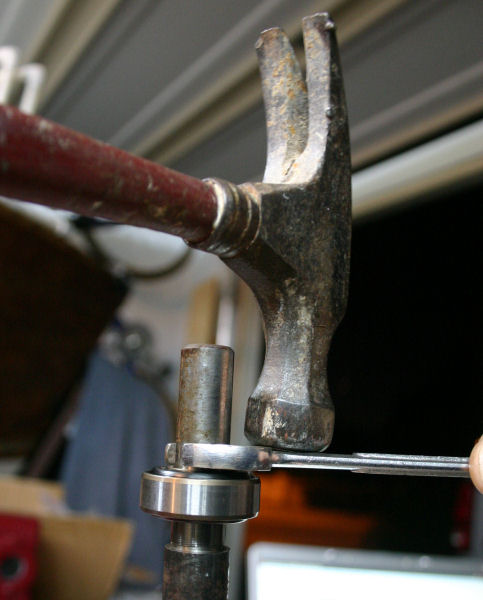
I was able to use my bearing puller to remove the two bearings from the quill but because the quill is so long, my puller didn't have the reach to install the bearings. Instead, needed to use "universal" tools........claw hammer and 5/8" open end wrench.
First bearing to install is the one on the splined end of shaft (I'll call it rear bearing). I wasn't thinking initially and I installed the opposite side first. Problem with that is you cannot later install the rear bearing since it is located up inside the quill housing. This pic shows the mistake of installing the front bearing. It does however give you a good view of the hammer and open end wrench bearing assembly method. As long as you use caution when starting the bearing to make sute that it goes on straight, this seemed to be a pretty good method. After I installed the front bearing up tight up against the shoulder, I realized my mistake and had to use my puller to remove it before I could proceed.
.
.
.
.
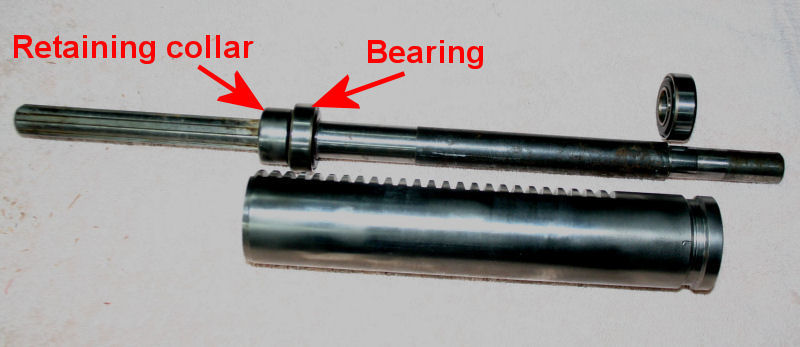
Using the same hammer and wrench method, installed the bearing on the splined end. Once that bearing is installed tightly up against the shoulder, you butt the retaining collar up against the bearing and secure it onto the shaft with it's set screw.
.
.
.
.
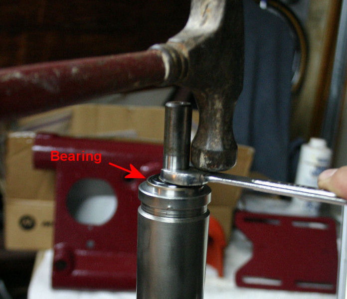
The shaft is installed into the quill housing from the backside and the front bearing is then installed. With the front bearing installed tightly up against the shaft shoulder, the bearing still stuck out a 1/4" or so. I thought something was wrong. I picked up the quill assembly and saw that there was a a lot of forward to backward play when pulling and pushing on the shaft. I was able to slide the shaft back and forth in the quill housing 1/4". This made me question if the back bearing was still properly installed up against it's shoulder so I pressed the shaft out, removing the front bearing, and clearly saw that the back bearing WAS in the correct position so I reinstalled the front bearing.
.
.
.
.
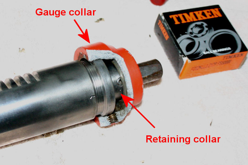
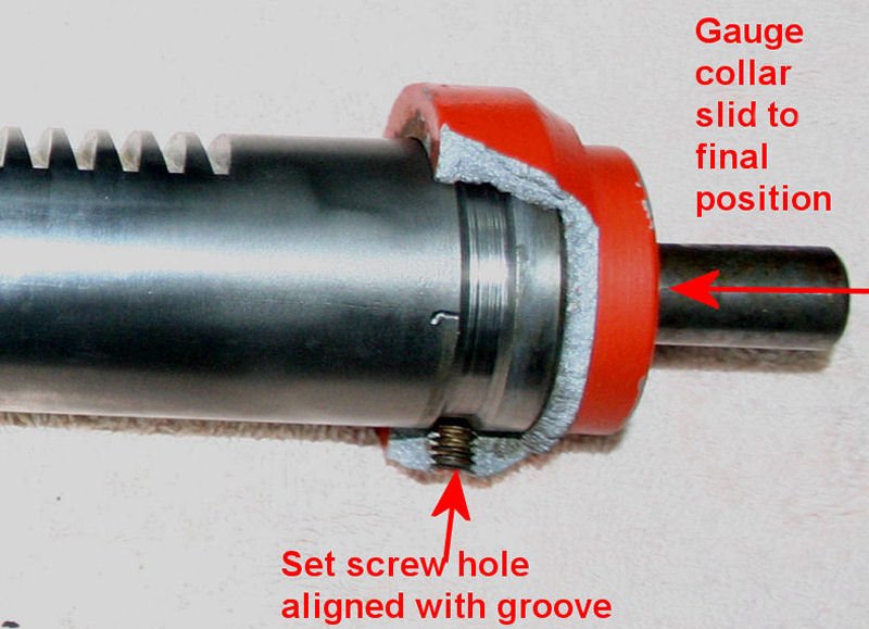
I then figured out that the play is eliminated by the retaining collar contacting up against the inside suface of the gauge collar. As you recall, I broke the original gauge collar when I removed it so it gave me the chance to see the assembly as if in cross section. I was kind of glad that I could see the innards! The gauge collar isn't installed all the way in the photo so that you can see the relationship with the retaining collar.
.
.
.
.
With the gauge collars in it's final position, it eliminates the back and forth play in the shaft. I now see why it's called a "gauge collar" since it gauges the distance between the groove position and retaining collar. That's my logic and I'm sticking to it (yet open to discussion however).
.
.
.
.
.
Next to do.....reassembly motor after painting....