Caster Upgrade Issue
Moderator: admin
Caster Upgrade Issue
I recently performed the caster upgrade and now have noticed there is a minor issue of interference of the caster with the foot levers that extend and retract the casters. I didn't check yet to see if the levers are held in place by a set screw or a roll pin, so as to be able to move it back a little. Just a little annoying if wheel is turned just right or should I say wrong.
Neal
Mark V 500, Mark V 500 Power Pro, SS mounted Planer, Jointer, Bandsaw, Belt Sander, Jig Saw, Nova G3, Universal Tool Rest
Mark V 500, Mark V 500 Power Pro, SS mounted Planer, Jointer, Bandsaw, Belt Sander, Jig Saw, Nova G3, Universal Tool Rest
-
JPG

- Platinum Member
- Posts: 35600
- Joined: Wed Dec 10, 2008 7:42 pm
- Location: Lexington, Ky (TAMECAT territory)
neal560sl wrote:I recently performed the caster upgrade and now have noticed there is a minor issue of interference of the caster with the foot levers that extend and retract the casters. I didn't check yet to see if the levers are held in place by a set screw or a roll pin, so as to be able to move it back a little. Just a little annoying if wheel is turned just right or should I say wrong.
There have been two(actually three) versions of the casters that vary in the position of the foot pedal. The earlier version had the foot pedal almost out to the end. The later version relocated the foot pedal towards the center.
AIUI, the older model will interfere with the new larger casters.
The foot pedal is attached to the cam shaft by a tension pin. A new hoile could be(and has been) drilled and the foot pedals moved. Care must be taken to ensure the hole is properly 'oriented'.
╔═══╗
╟JPG ╢
╚═══╝
Goldie(Bought New SN 377425)/4" jointer/6" beltsander/12" planer/stripsander/bandsaw/powerstation /Scroll saw/Jig saw /Craftsman 10" ras/Craftsman 6" thicknessplaner/ Dayton10"tablesaw(restoredfromneighborstrashpile)/ Mark VII restoration in 'progress'/ 10E[/size](SN E3779) restoration in progress, a 510 on the back burner and a growing pile of items to be eventually returned to useful life. - aka Red Grange
╟JPG ╢
╚═══╝
Goldie(Bought New SN 377425)/4" jointer/6" beltsander/12" planer/stripsander/bandsaw/powerstation /Scroll saw/Jig saw /Craftsman 10" ras/Craftsman 6" thicknessplaner/ Dayton10"tablesaw(restoredfromneighborstrashpile)/ Mark VII restoration in 'progress'/ 10E[/size](SN E3779) restoration in progress, a 510 on the back burner and a growing pile of items to be eventually returned to useful life. - aka Red Grange
-
JPG
- Platinum Member
- Posts: 35600
- Joined: Wed Dec 10, 2008 7:42 pm
- Location: Lexington, Ky (TAMECAT territory)
Good plan!neal560sl wrote:I figured it wasn't normal. I will use it a little more and see how bad it bothers me. Thanks for the reply.
Taking the casters apart and reassembling can by trying(especially the second part if both are 'apart' simultaneously).
Other than that and the hole alignment detail, moving the footpedal is a short project. If possible, only take the pin out securing the footpedal so it can slide to the new hole and the pin replaced there. A good center punch to create the starting location of the hole for the drill bit will be helpful to get the bit started straight to the round shaft. A way to hold the shaft 'securely' will also help!
╔═══╗
╟JPG ╢
╚═══╝
Goldie(Bought New SN 377425)/4" jointer/6" beltsander/12" planer/stripsander/bandsaw/powerstation /Scroll saw/Jig saw /Craftsman 10" ras/Craftsman 6" thicknessplaner/ Dayton10"tablesaw(restoredfromneighborstrashpile)/ Mark VII restoration in 'progress'/ 10E[/size](SN E3779) restoration in progress, a 510 on the back burner and a growing pile of items to be eventually returned to useful life. - aka Red Grange
╟JPG ╢
╚═══╝
Goldie(Bought New SN 377425)/4" jointer/6" beltsander/12" planer/stripsander/bandsaw/powerstation /Scroll saw/Jig saw /Craftsman 10" ras/Craftsman 6" thicknessplaner/ Dayton10"tablesaw(restoredfromneighborstrashpile)/ Mark VII restoration in 'progress'/ 10E[/size](SN E3779) restoration in progress, a 510 on the back burner and a growing pile of items to be eventually returned to useful life. - aka Red Grange
I finished installing 3”]21932[/ATTACH]JPG40504 wrote:Good plan!
Taking the casters apart and reassembling can by trying(especially the second part if both are 'apart' simultaneously).
Other than that and the hole alignment detail, moving the footpedal is a short project. If possible, only take the pin out securing the footpedal so it can slide to the new hole and the pin replaced there. A good center punch to create the starting location of the hole for the drill bit will be helpful to get the bit started straight to the round shaft. A way to hold the shaft 'securely' will also help!
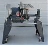
I found a box of 3” casters that I brought a few years ago to install on the MINI and SHORTY Shopsmiths I was selling. The customers was not interested in the additional cost at that time so they were packed in a box and forgotten. I made a metal drilling template for the new holes using a prior post for hole location. I drilled one leg and installed the casters. The leg was only lifted at the second lift wedge position. I determined new hole locations (1 ¼” higher) and made a new drilling template.
[ATTACH]21933[/ATTACH]
I noticed that the foot pedal could contact the caster closest to it. I marked the location of the foot pedal lever and the lift rod near the lift wedge for alignment when the foot pedal is moved 1 ½” further from the lift wedge. I used a large flat blade screwdriver between the caster housing and the lift wedge to ply the lift rod from the housings. I used the screwdriver to install the lift rod back into the housings. I did not remove any roll pins from the smaller connecting rod between the two housings. I secured the lift rod in a vise and used a 8p common nail with the end ground flat to remove the 5/32” foot pedal roll pin. I used vise grips to initially hold the nail to prevent the nail from bending and damage to my fingers. I center punched the lift rod about 2 ¼” from the lift wedge and drilled a 5/32” centered hole. Using the prior marks and the nail to position the foot pedal, I hammered the 5/32” roll pin back into the foot pedal pushing out the nail. The following picture is with one caster set foot pedal in the original position and the other caster set with the new foot pedal location.
[ATTACH]21934[/ATTACH]
The new leg holes were perfect in that it allows the casters to be moved by hand when the legs were setting on the floor. The first and second lift positions allowed the Shopsmith to be easy to move now. This was quite an improvement allowing for my rough concrete floors.
- Attachments
-
- 100_0668.JPG (22.49 KiB) Viewed 2728 times
-
- 100_0679.JPG (18.66 KiB) Viewed 2732 times
-
- 100_0675.JPG (21.6 KiB) Viewed 2734 times
Bill Mayo bill.mayo@verizon.net
Shopsmith owner since 73. Sell, repair and rebuild Shopsmith, Total Shop & Wood Master headstocks, SPTs, attachments, accessories and parts. US Navy 1955-1975 (FTCS/E-8)
Shopsmith owner since 73. Sell, repair and rebuild Shopsmith, Total Shop & Wood Master headstocks, SPTs, attachments, accessories and parts. US Navy 1955-1975 (FTCS/E-8)
Additional Infro. I cut the 8p common nail to where it just pushed the rollpin just out of the rod when the nail head hit the foot pedal. This way the roll pin was still in one half of the foot pedal. I used the nail to align the foot pedal to the new hole and holding the nail, hammered the roll pin fully back into the foot pedal. Be sure to mark the rod and foot pedal so it will be aligned correctly in the new hole.
One of my next projects is to see what has to be done to install the 3" casters on the Power Station since Shopsmith stated that they do not fit. Always some fun project to play with.
One of my next projects is to see what has to be done to install the 3" casters on the Power Station since Shopsmith stated that they do not fit. Always some fun project to play with.
Bill Mayo bill.mayo@verizon.net
Shopsmith owner since 73. Sell, repair and rebuild Shopsmith, Total Shop & Wood Master headstocks, SPTs, attachments, accessories and parts. US Navy 1955-1975 (FTCS/E-8)
Shopsmith owner since 73. Sell, repair and rebuild Shopsmith, Total Shop & Wood Master headstocks, SPTs, attachments, accessories and parts. US Navy 1955-1975 (FTCS/E-8)
-
JPG
- Platinum Member
- Posts: 35600
- Joined: Wed Dec 10, 2008 7:42 pm
- Location: Lexington, Ky (TAMECAT territory)
billmayo wrote:Additional Infro. I cut the 8p common nail to where it just pushed the rollpin just out of the rod when the nail head hit the foot pedal. This way the roll pin was still in one half of the foot pedal. I used the nail to align the foot pedal to the new hole and holding the nail, hammered the roll pin fully back into the foot pedal. Be sure to mark the rod and foot pedal so it will be aligned correctly in the new hole.
One of my next projects is to see what has to be done to install the 3" casters on the Power Station since Shopsmith stated that they do not fit. Always some fun project to play with.
Are you aware of my reverse the cam shaft 'alteration' that places the foot pedal facing towards the outside of the legs of the power station? If I can locate the post, I will link it.
I found it , but it does not change the location of the casters.
https://forum.shopsmith.com/viewtopic.php?t=9019
╔═══╗
╟JPG ╢
╚═══╝
Goldie(Bought New SN 377425)/4" jointer/6" beltsander/12" planer/stripsander/bandsaw/powerstation /Scroll saw/Jig saw /Craftsman 10" ras/Craftsman 6" thicknessplaner/ Dayton10"tablesaw(restoredfromneighborstrashpile)/ Mark VII restoration in 'progress'/ 10E[/size](SN E3779) restoration in progress, a 510 on the back burner and a growing pile of items to be eventually returned to useful life. - aka Red Grange
╟JPG ╢
╚═══╝
Goldie(Bought New SN 377425)/4" jointer/6" beltsander/12" planer/stripsander/bandsaw/powerstation /Scroll saw/Jig saw /Craftsman 10" ras/Craftsman 6" thicknessplaner/ Dayton10"tablesaw(restoredfromneighborstrashpile)/ Mark VII restoration in 'progress'/ 10E[/size](SN E3779) restoration in progress, a 510 on the back burner and a growing pile of items to be eventually returned to useful life. - aka Red Grange
Power Station Casters
NO, Thanks for the pictures. Excellant way to be able to use the casters. I see why there is a problem with the bigger casters, no swivel room. It looks like I would have to use at least a 1 1/2" thick spacers with new mounting holes and cut the caster assembly a couple inches closer together. Some thing to think about putting a caster kit together once I get my modified Power Station operating.JPG40504 wrote:Are you aware of my reverse the cam shaft 'alteration' that places the foot pedal facing towards the outside of the legs of the power station? If I can locate the post, I will link it.
I found it , but it does not change the location of the casters.
https://forum.shopsmith.com/viewtopic.php?t=9019
Bill Mayo bill.mayo@verizon.net
Shopsmith owner since 73. Sell, repair and rebuild Shopsmith, Total Shop & Wood Master headstocks, SPTs, attachments, accessories and parts. US Navy 1955-1975 (FTCS/E-8)
Shopsmith owner since 73. Sell, repair and rebuild Shopsmith, Total Shop & Wood Master headstocks, SPTs, attachments, accessories and parts. US Navy 1955-1975 (FTCS/E-8)