
JPG or another motor pro...
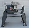
I bought a good size milling machine. Thing is, after many years and someone elses fiddling the wires to the switch have been replaced so old wiring docs don't measure up.
I took these pics. The motor is capable of 220 and is supposed to be reversible. I gather the 4 wires shown in the pic are the coil leads. So how would you guys suggest to fit in a reversing switch? Or, how to tell what wires to fit the switch to?
I went through this when I got my metal lathe and JPG led my charge last time so here I go again.
[ATTACH]23780[/ATTACH]
[ATTACH]23781[/ATTACH]
[ATTACH]23782[/ATTACH]
[ATTACH]23783[/ATTACH]
It's wired 110 now as you can see in the last pic. The wires to the right of the black, gray, yellow, red go to the switch.
motor question..not a SS motor
Moderator: admin
motor question..not a SS motor
- Attachments
-
- PA100322 (800x600).jpg (89.81 KiB) Viewed 1750 times
-
- PA100323 (800x600).jpg (100.99 KiB) Viewed 1747 times
-
- wiring diagram (800x600).jpg (109.93 KiB) Viewed 1754 times
-
- PA100325 (800x600).jpg (95.77 KiB) Viewed 1751 times
-
freedomlives
- Gold Member
- Posts: 59
- Joined: Wed May 01, 2013 10:48 am
- Location: Slovakia
- Contact:
Why is the blue neutral wire connected to the green/yellow-stripe ground wire? That should not be! The ground wire needs to be attached to the metal case of the motor. Right now, if something burned up in the motor and a live wire came to touch the metal case, it and probably the whole machine would be at 120V. Is there not a screw inside that wiring box to attach the ground wire to in order to connect it to the metal chasis?
Good catch. Let me get back out there and see and or rig it up that way. Totally went right by that.
Found the proper location for green after some messing around. I managed to wire up the electronics box in back as much had been disconnected. Just missed this up at the motor. So anyone have any thoughts on which 2 of the 4 (gray, black, red, yellow) need to be switched to run reverse?
Found the proper location for green after some messing around. I managed to wire up the electronics box in back as much had been disconnected. Just missed this up at the motor. So anyone have any thoughts on which 2 of the 4 (gray, black, red, yellow) need to be switched to run reverse?
Normally, any 110//220 VAC reversible motor has 6 wire leads going into the motor. Four for the run windings and two for the start windings. Get an ohm meter and check the resistance between each of the two wires. The run windings should be around 1 to 3 ohms and the start windings from 4 to 7 ohms. You should not get this low resistance between all combinations of wires, only 2 sets of wires. Also check that no wire is shorted to ground. You only have to switch the start winding wires for reverse operation. Let us know what the ohm readings were for each pair of wires along with their color. Again, normally red and black are the start windings if the motor wires are color coded to the US standard.holsgo wrote:Good catch. Let me get back out there and see and or rig it up that way. Totally went right by that.
Found the proper location for green after some messing around. I managed to wire up the electronics box in back as much had been disconnected. Just missed this up at the motor. So anyone have any thoughts on which 2 of the 4 (gray, black, red, yellow) need to be switched to run reverse?
Bill Mayo bill.mayo@verizon.net
Shopsmith owner since 73. Sell, repair and rebuild Shopsmith, Total Shop & Wood Master headstocks, SPTs, attachments, accessories and parts. US Navy 1955-1975 (FTCS/E-8)
Shopsmith owner since 73. Sell, repair and rebuild Shopsmith, Total Shop & Wood Master headstocks, SPTs, attachments, accessories and parts. US Navy 1955-1975 (FTCS/E-8)
-
JPG

- Platinum Member
- Posts: 35600
- Joined: Wed Dec 10, 2008 7:42 pm
- Location: Lexington, Ky (TAMECAT territory)
'Supposed' to be reversible.
Says who?
The plate does not.
I think the wires are the run windings. The "+" symbols on the plate indicate wires 'connected'.
i.e. 115v.................230v
.....L1,bk,ye............L1,bk
.....L2,gy,rd............L2,gy
............................rd,ye
P.S. Please do not reverse the polarity of the coils!!!!!!
Says who?
The plate does not.
I think the wires are the run windings. The "+" symbols on the plate indicate wires 'connected'.
i.e. 115v.................230v
.....L1,bk,ye............L1,bk
.....L2,gy,rd............L2,gy
............................rd,ye
P.S. Please do not reverse the polarity of the coils!!!!!!
╔═══╗
╟JPG ╢
╚═══╝
Goldie(Bought New SN 377425)/4" jointer/6" beltsander/12" planer/stripsander/bandsaw/powerstation /Scroll saw/Jig saw /Craftsman 10" ras/Craftsman 6" thicknessplaner/ Dayton10"tablesaw(restoredfromneighborstrashpile)/ Mark VII restoration in 'progress'/ 10E[/size](SN E3779) restoration in progress, a 510 on the back burner and a growing pile of items to be eventually returned to useful life. - aka Red Grange
╟JPG ╢
╚═══╝
Goldie(Bought New SN 377425)/4" jointer/6" beltsander/12" planer/stripsander/bandsaw/powerstation /Scroll saw/Jig saw /Craftsman 10" ras/Craftsman 6" thicknessplaner/ Dayton10"tablesaw(restoredfromneighborstrashpile)/ Mark VII restoration in 'progress'/ 10E[/size](SN E3779) restoration in progress, a 510 on the back burner and a growing pile of items to be eventually returned to useful life. - aka Red Grange
Looks very true. If both sets of wires have the same ohm readings, then do not reverse any wires. I just touch the power cord plug into the outlet when playing with unknown motor wiring. Reversing one of the run windings will cause an electrical rotor lockup and the motor will make quite a loud noise when this happens. A second or less of power in this case will not cause any damage to the motor.JPG40504 wrote:'Supposed' to be reversible.
Says who?
The plate does not.
I think the wires are the run windings. The "+" symbols on the plate indicate wires 'connected'.
i.e. 115v.................230v
.....L1,bk,ye............L1,bk
.....L2,gy,rd............L2,gy
............................rd,ye
P.S. Please do not reverse the polarity of the coils!!!!!!
Bill Mayo bill.mayo@verizon.net
Shopsmith owner since 73. Sell, repair and rebuild Shopsmith, Total Shop & Wood Master headstocks, SPTs, attachments, accessories and parts. US Navy 1955-1975 (FTCS/E-8)
Shopsmith owner since 73. Sell, repair and rebuild Shopsmith, Total Shop & Wood Master headstocks, SPTs, attachments, accessories and parts. US Navy 1955-1975 (FTCS/E-8)
This may be an incorrect assumption on my part but....this mill is sold under various labels and has been for 20 years. Some versions claim they are reversible, others are wired for 220 from the factory etc. I'm making a guess that this one may be reversible based on all of the other versions that are. Each function claimed by each label on the machine raises the price or lowers it.
I might be wrong but figured I would ask.
I also saw many similar on the 6x26 forum for this machine....just kinda hoping I can reverse it, but not willing to kill the machine in the process.
I might be wrong but figured I would ask.
I also saw many similar on the 6x26 forum for this machine....just kinda hoping I can reverse it, but not willing to kill the machine in the process.
-
JPG
- Platinum Member
- Posts: 35600
- Joined: Wed Dec 10, 2008 7:42 pm
- Location: Lexington, Ky (TAMECAT territory)
Q1 Are the wires totally free from any external connections when making the 'test'? That means all four are flapping in the breeze.holsgo wrote:Here's the test
Black yellow is 1.3
Red gray is 0
Red yellow is 0
Red black is 14 when first touch and drops to .8.
Wish I knew more about motors.
Q2 When measuring the 14 / .8, what happens if you quickly reverse the meter leads?
Q3 What kind of meter? led/digital or analog/needle/d'arsonval
Will be 'pondering in the mean time.
This does not jive with previous 'opinion'.
╔═══╗
╟JPG ╢
╚═══╝
Goldie(Bought New SN 377425)/4" jointer/6" beltsander/12" planer/stripsander/bandsaw/powerstation /Scroll saw/Jig saw /Craftsman 10" ras/Craftsman 6" thicknessplaner/ Dayton10"tablesaw(restoredfromneighborstrashpile)/ Mark VII restoration in 'progress'/ 10E[/size](SN E3779) restoration in progress, a 510 on the back burner and a growing pile of items to be eventually returned to useful life. - aka Red Grange
╟JPG ╢
╚═══╝
Goldie(Bought New SN 377425)/4" jointer/6" beltsander/12" planer/stripsander/bandsaw/powerstation /Scroll saw/Jig saw /Craftsman 10" ras/Craftsman 6" thicknessplaner/ Dayton10"tablesaw(restoredfromneighborstrashpile)/ Mark VII restoration in 'progress'/ 10E[/size](SN E3779) restoration in progress, a 510 on the back burner and a growing pile of items to be eventually returned to useful life. - aka Red Grange