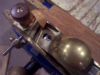
The first pic is the table lift crank with lever disassembled. (BEFORE)
- b4 table lever.jpg (363.52 KiB) Viewed 21483 times
- after crank.jpg (345.12 KiB) Viewed 21493 times
- new parts.jpg (327 KiB) Viewed 21478 times
The white thingey is a spacer to hold the original 'pinion knob' centered. It is made from a paper roll core and is slightly shorter than the pinion knob. The core had 8 webs between the od(7/8") and the id. The id was 'sliced' at 4 places equally spaced. This allows the 'thingey' to slip over the crank shaft.
The washer goes between the new crank and the original pinion knob. The clamping force when the lock wingnut is tightened is from the crank through the washer to the pinion knob and to the table pinion.
The fourth pic shows the spacer(thingey) on the crank shaft.
- spacer on shaft.jpg (290 KiB) Viewed 21483 times
- hit crank limit.jpg (285.74 KiB) Viewed 21482 times
This 'alteration' does NOT modify any existing parts and is therefore totally reversible(assuming you keep track of the newly unused parts).
EDIT: 'Thingy' has been replaced with a more durable part.
http://www.shopsmith.com/ss_forum/viewt ... 20#p163020
Also see other(simpler) solution below.