
Here is the situation, I've been working on making some pendants but today I ran in to an issue that has me pretty much stopped in my tracks.
Forward
I purchased a faceplate that has a center hole and a series of "off-center" holes. I have this mounts by way of a 3/8" stud that is mounted in a shopsmith router chuck by way of a 3/8" to 1/2" adapter. That faceplate then has a series of screw holes that allows the secondary plate to be mounted in any of the 24 locations available. Don't worry pictures are coming.
To the secondary plate has screw holes to mount a waste block. Like other projects the waste block becomes the place the project is mounted for turning. So first I true up the block so it runs round and flat. Then I turn the area where the pendent will mount, a smaller area so I can tape the project piece down but still get my fingers in to remove it (held on with double side tape).
As mentioned here are the pictures:
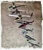
[ATTACH]25069[/ATTACH]
This is the collection of parts.
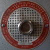
[ATTACH]25070[/ATTACH]
When assembled it looks like this. Note the "0" and "0" are lined up.
This is where I trued up the block and have it ready to mount the pendant.
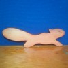
[ATTACH]25071[/ATTACH]
This show the front or working face.
[ATTACH]25072[/ATTACH]
The pieces have been rotated 180 degrees.
Problem
This attachment is normal sold with a MT2 to 3/8" drive for use in more conventional lathes. I'm using a cut off bolt which I made to turn bottle stoppers and that sort of thing. It has worked well for that and in fact I have made two of these for convenience. I tried both of them.
In this video things are setup and working pretty much the way it is expected to work.
https://www.youtube.com/watch?v=wFk890juj5k
The lathe is running at 1000 rpm and I would have no problem making a pendant and in fact I have.
In this video the index was changed so it is 180 degrees from the previous setting.
https://www.youtube.com/watch?v=WXkWkZn8BPk
As you can see it is wobble time, this would be very difficult to do any fine turning with it this way.
I stepped back to just the faceplate for this video.
https://www.youtube.com/watch?v=DBD36l-bO5M
Indeed the issues is clearly presenting it self already.
So as of right now the indexing is not functional except at "0" "0".
My problem is which part is causing the issue. It could be the bolt but the faceplate seems to run pretty well on it side edge.... the faceplate could either be drilled a bit off or the face might not be flat.
I plan to contact the seller but I though I give you guys a shot at providing some input. I'm no lathe expert so maybe you will see something amiss.
Worse case I guess I could have an adapter made, 5/8" shopsmith to 3/8" x 16........
Ed
Today in the shop (turning problem)
Moderator: admin
Today in the shop (turning problem)
- Attachments
-
- IMG_2889sc.jpg (259.22 KiB) Viewed 2584 times
-
- IMG_2890sc.jpg (266.05 KiB) Viewed 2579 times
-
- IMG_2891sc.jpg (262.18 KiB) Viewed 2582 times
-
- IMG_2892sc.jpg (267.65 KiB) Viewed 2582 times
-
rcplaneguy
- Platinum Member
- Posts: 549
- Joined: Mon Sep 23, 2013 6:33 pm
- Location: Chapel Hill, NC
-
JPG

- Platinum Member
- Posts: 35598
- Joined: Wed Dec 10, 2008 7:42 pm
- Location: Lexington, Ky (TAMECAT territory)
In all three videos the base plate(attached to the drive screw/shaft) wobbles.
If you are truing the mount block with the secondary plate set to '0', then when set to 180, the wobble of the base plate will be doubled since the mounting block was 'trued' to a wobbling base plate. The greater od of the mounting block will increase apparent wobble further.
Measure the od of the screw and the id and od of the sleeve.
I believe all the wobble is due to runout between the 1/2" router adapter and the base plate. A bent screw would be culpable as well.
I have two observations which lead to two questions.
1) Is there a cone like projection on one end one the base plate which mates with the concave cone shape in the end of the secondary plate? Orrr, is there one on the mt2 mount you are not usingf?(I now see it is flat on the table)
2) The mounting block is threaded in the center bore. Relevant or not?
╔═══╗
╟JPG ╢
╚═══╝
Goldie(Bought New SN 377425)/4" jointer/6" beltsander/12" planer/stripsander/bandsaw/powerstation /Scroll saw/Jig saw /Craftsman 10" ras/Craftsman 6" thicknessplaner/ Dayton10"tablesaw(restoredfromneighborstrashpile)/ Mark VII restoration in 'progress'/ 10E[/size](SN E3779) restoration in progress, a 510 on the back burner and a growing pile of items to be eventually returned to useful life. - aka Red Grange
-
terrydowning
- Platinum Member
- Posts: 1678
- Joined: Mon Jul 19, 2010 3:26 pm
- Location: Windsor, CO
I don't get it.
Why are you setting the indexed plates 180 degrees out?
Why are you setting the indexed plates 180 degrees out?
--
Terry
Copy and paste the URLs into your browser if you want to see the photos.
1955 Shopsmith Mark 5 S/N 296860 Workshop and Tools
https://1drv.ms/i/s!AmpX5k8IhN7ahFCo9VvTDsCpoV_g
Public Photos of Projects
http://sdrv.ms/MaXNLX
Terry
Copy and paste the URLs into your browser if you want to see the photos.
1955 Shopsmith Mark 5 S/N 296860 Workshop and Tools
https://1drv.ms/i/s!AmpX5k8IhN7ahFCo9VvTDsCpoV_g
Public Photos of Projects
http://sdrv.ms/MaXNLX
-
dusty

- Platinum Member
- Posts: 21530
- Joined: Wed Nov 22, 2006 6:52 am
- Location: Tucson (Wildcat Country), Arizona
Ed, I assume you initially trued the block with it attached to the faceplate and the faceplate aligned 0/0. I further assume that if you return to that setup, the vibration goes back to normal.
If that is the case, it seems to me that somehoe the black simply gets off center to the faceplate.
I'll be watching to see what turns up.
If that is the case, it seems to me that somehoe the black simply gets off center to the faceplate.
I'll be watching to see what turns up.
"Making Sawdust Safely"
Dusty
Sent from my Dell XPS using Firefox.
Dusty
Sent from my Dell XPS using Firefox.
I would be suspicious of the 3/8 stud/washer/nut/adapter assembly. A one piece machined arbor would be a better way to go.
Tapmatic 1/2" Straight Shank Arbor with Threaded Mount, 3/8"-24 Thread
[ATTACH]25074[/ATTACH]
Tapmatic 1/2" Straight Shank Arbor with Threaded Mount, 3/8"-24 Thread
[ATTACH]25074[/ATTACH]
- Attachments
-
- 12arbor.jpg (46.38 KiB) Viewed 2536 times
Ron Dyck
==================================================================
10ER #23430, 10ER #84609, 10ER #94987,two SS A-34 jigsaws for 10ER.
1959 Mark 5 #356595 Greenie, SS Magna Jointer, SS planer, SS bandsaw, SS scroll saw (gray), DC3300,
==================================================================
10ER #23430, 10ER #84609, 10ER #94987,two SS A-34 jigsaws for 10ER.
1959 Mark 5 #356595 Greenie, SS Magna Jointer, SS planer, SS bandsaw, SS scroll saw (gray), DC3300,
-
JPG
- Platinum Member
- Posts: 35598
- Joined: Wed Dec 10, 2008 7:42 pm
- Location: Lexington, Ky (TAMECAT territory)
BINGO!!!!!!!!!!!!rpd wrote:I would be suspicious of the 3/8 stud/washer/nut/adapter assembly. A one piece machined arbor would be a better way to go.
Tapmatic 1/2" Straight Shank Arbor with Threaded Mount, 3/8"-24 Thread
[ATTACH]25074[/ATTACH]
╔═══╗
╟JPG ╢
╚═══╝
Goldie(Bought New SN 377425)/4" jointer/6" beltsander/12" planer/stripsander/bandsaw/powerstation /Scroll saw/Jig saw /Craftsman 10" ras/Craftsman 6" thicknessplaner/ Dayton10"tablesaw(restoredfromneighborstrashpile)/ Mark VII restoration in 'progress'/ 10E[/size](SN E3779) restoration in progress, a 510 on the back burner and a growing pile of items to be eventually returned to useful life. - aka Red Grange
╟JPG ╢
╚═══╝
Goldie(Bought New SN 377425)/4" jointer/6" beltsander/12" planer/stripsander/bandsaw/powerstation /Scroll saw/Jig saw /Craftsman 10" ras/Craftsman 6" thicknessplaner/ Dayton10"tablesaw(restoredfromneighborstrashpile)/ Mark VII restoration in 'progress'/ 10E[/size](SN E3779) restoration in progress, a 510 on the back burner and a growing pile of items to be eventually returned to useful life. - aka Red Grange
Thank you all for your responses! I'm having a gardening day so thus far I have just done a skim read of the reply's.
I have looked at the screw centers I have made, they both pass the roll test as best as I could tell. Anytime threads are involved it is more difficult to view none the less with a back light I see a pretty uniform pattern. This does not mean that they are not the problem.....
The indexing is every 15 degrees and it does not take long before the issue starts showing up. Yes it is very pronounced when you are 180 degrees out which is indicative of the possible issues.
I think it might be well for me to have a special shopsmith version made to order, one that will eliminate issues on my end, thus either solving the problem or moving it to the faceplate.
I'll be back tonight to digest what has been written.
Ed
Today was a washout of shop time, to much gardening to do. I'm hoping it rains for part of tomorrow so I can have more time to look at this situation.
To answer the two questions, the cone looking hole is for a screw that would attach say a bottle stopper directly to the plate. This is how some bottle stoppers are done, the bottom is done first then threaded and attached via a 3/8" x 16 tpi mounting stud.
The mounting block was threaded so I could turn the back side flat, step one in the process. The block is then turned so the flat sits against the second plate where the 4 screws mount it. The faceplate is then attached to the second plate via a set of screws. This is when the block is turned true and the step is made on the front. The 3/8" x 16 screw doesn't come in to contact with the block except for the original flatting process.
Does that make sense?
Ed
JPG40504 wrote:In all three videos the base plate(attached to the drive screw/shaft) wobbles.
If you are truing the mount block with the secondary plate set to '0', then when set to 180, the wobble of the base plate will be doubled since the mounting block was 'trued' to a wobbling base plate. The greater od of the mounting block will increase apparent wobble further.
Measure the od of the screw and the id and od of the sleeve.
I believe all the wobble is due to runout between the 1/2" router adapter and the base plate. A bent screw would be culpable as well.
I have two observations which lead to two questions.
1) Is there a cone like projection on one end one the base plate which mates with the concave cone shape in the end of the secondary plate? Orrr, is there one on the mt2 mount you are not usingf?(I now see it is flat on the table)
2) The mounting block is threaded in the center bore. Relevant or not?