Fixture for my old OPR

This is a forum for intermediate to advanced woodworkers. Show off your projects or share your ideas.

Moderator: admin

Post Reply
User avatar
reible
Platinum Member
Posts: 11283
Joined: Thu Jul 20, 2006 12:08 pm
Location: Aurora, IL

Fixture for my old OPR

Post by reible »

This is a pin off set fixture. It is nothing fancy nor does it have any exacting size requirements or measurements. Not only that but it also works on the shopsmith for doing some offset drilling.... so what have you got to lose in checking this out??

This would likely work with the newer OPR but I don't have one to check it out on. Feel free to make one and let us know if it does work.

This is the whole design:
1dddd.jpg
1dddd.jpg (55.21 KiB) Viewed 9475 times
Parts wise this is a cheap piece of (3/4") handy ply that was left over after some project or another. The over all size was pretty much what I had left over and then resized to even numbers. If you want to use it on your shopsmith in drilling operations make sure that you can get a good fit based on the depth of the drill press.

If your piece is squared then the process of locating the holes can be done as shown. The center most hole is for a threaded insert that fits the "pins" of the OPR. I forget the thread, is it 10-32??? Anyway check that and find the correct bit size to drill the hole and then insert. Note the measurement places it centered on the width and 9" back. Again this is not critical but just what I used.

The other two holes are for shopsmith t-nuts. If you wish you can just use clamps to hold it in place and indeed that is what I had to do for some of the drilling I did with the jig and it worked fine.

I neglected to take any photos of it just sitting on the shopsmith main table for the drilling operation so you will have to make do with this photo of it on the OPR.
IMG_2898sc.jpg
IMG_2898sc.jpg (86.5 KiB) Viewed 9475 times
Here is where I needed to go with clamps to hold it in place:
IMG_2895sc.jpg
IMG_2895sc.jpg (98.75 KiB) Viewed 9475 times
In the next post I'll show you how it works.

Ed
{Knight of the Shopsmith} [Hero's don't wear capes, they wear dog tags]
User avatar
reible
Platinum Member
Posts: 11283
Joined: Thu Jul 20, 2006 12:08 pm
Location: Aurora, IL

Re: Fixture for my old OPR

Post by reible »

I have a project that shows how to use this fixture so I'm going to show what I did and perhaps that is the best way to present this.

What I'm making is a template to use with the OPR to make a Longworth chuck. That thread is here:

http://www.shopsmith.com/ss_forum/gener ... 18992.html

Some of this material will be in the other thread presented in a slightly different way. That thread will also reference this thread.

I did a layout of the template on a square piece of plywood. The end part will be round but it is easier to do the layout when you can go corner to corner and find the center of the piece. Then adding a vertical and horizontal line and you end up with the piece segmented by 8 lines. It just so happens that is what we need to make this, nice how that worked out.

The lines are hard to see but this is about the best I have on hand to show it.
IMG_2885sc.jpg
IMG_2885sc.jpg (150.34 KiB) Viewed 9470 times
We are not going to cover the hows and whys of all the lines and how I figured them out. The important thing is that there are holes what need to be placed at accurate locations based on other points located on the fixture. The first and most important starting point is the center hole. But first I wanted to get the fixture a bit more round. Since later I'll be truing it with the OPR I just cut within a 1/4" or so out side the line.
IMG_2886sc.jpg
IMG_2886sc.jpg (107.93 KiB) Viewed 9470 times
After taking my time and making sure I was on center I drilled the center hole.
IMG_2887sc.jpg
IMG_2887sc.jpg (131.33 KiB) Viewed 9470 times
At this point it is time to mount the fixture and set up to drill the 8 pivot holes. The holes are all equal distance from the center hole and are on one of the 8 lines that radiate out from the center. Since the holes are all the same distance from the center hole I can use that fact to locate the holes. I can do that by moving the fixture so the pin is off set from the drill press center line like this:
IMG_2890msc.jpg
IMG_2890msc.jpg (100.46 KiB) Viewed 9470 times
The pin is now where the arrow is pointing. The line from the pin to the spot I want to drill is then controlled as far as distance and I am left with just making sure it is on the line. The nice part is that all 8 holes are the same distance from the center pin and just need to be rotated into position.
IMG_2891sc.jpg
IMG_2891sc.jpg (95.94 KiB) Viewed 9470 times
Time for my supper so we will continue this later. I've got TV shows to watch at 7:00 and 8:00 (not the debates). So it might be a bit later.....

Ed
{Knight of the Shopsmith} [Hero's don't wear capes, they wear dog tags]
User avatar
reible
Platinum Member
Posts: 11283
Joined: Thu Jul 20, 2006 12:08 pm
Location: Aurora, IL

Re: Fixture for my old OPR

Post by reible »

All of the holes thus far have been 1/4" which is the same as the pin from the pin router. One could use either of the other two sizes, those being 3/8" and 1/2" but for me the 1/4" was a better choice for those holes. The next holes I will use a 3/8" bit. You will see why later. But first......

The 8 new holes are pivot locations. In this case they are used to create the arcs by placing the template on the pin and then drilling the two end points. Anyone have an idea why we need the end points? That will be obvious ones we get to the router table.

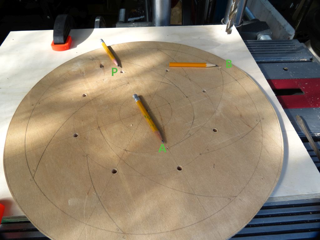
OK then lets look at that arc. In the next picture the "P" is the pivot point and the two parts of the arc are labeled "A" and "B". This design calls for 4 longer arcs and 4 shorter arcs. The one shown is for a longer arc.
IMG_2892msc.jpg
IMG_2892msc.jpg (112.67 KiB) Viewed 9445 times
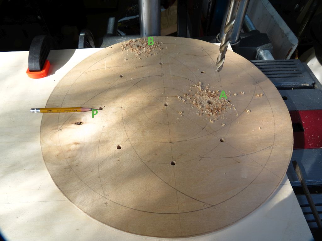
To locate the holes the point "P" is placed on the pin in the fixture. The two holes are then an equal distance from the pin and the other location is on the ray lines.
IMG_2893msc.jpg
IMG_2893msc.jpg (102.54 KiB) Viewed 9445 times
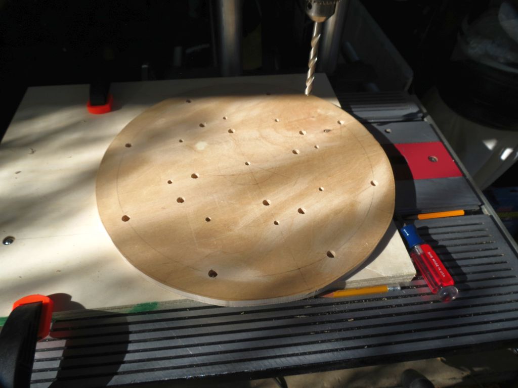
The template is then moved to the other 7 locations and those holes are drilled. The end result is this:
IMG_2894sc.jpg
IMG_2894sc.jpg (89.8 KiB) Viewed 9445 times
At this point the holes are drilled and we can move the fixture to the router table. Step one is to fix the distance from the pin to the pin side of the router bit. In this case I have a 1/4" solid carbide bit chucked up. With the fixture distance set the template is mounted on the pin and it is as simple as lowering the bit in a step and rotating the template around as it is cut into a pretty perfect circle. It takes a couple of steps to do this but it goes fast.

While you are at this point you can go to the actual work pieces and using the template as a guide trace around the outside of the circle to mark the work pieces. You can also use the template to locate and drill the center holes. Again I cut the work pieces with the bandsaw to sort of close to the line but staying outside the line as the router will be sizing it in just a moment.

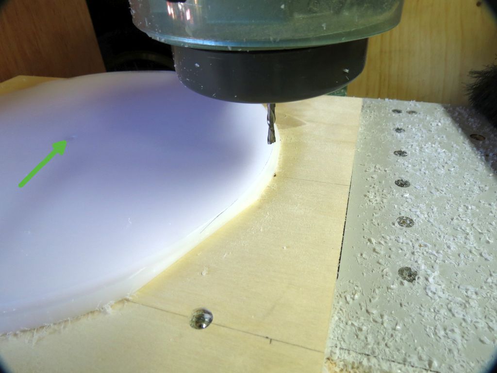
Using the same OPR set up you did to round the template you can round the two work pieces. I did take a picture but it not all that clear as to what is going on. The arrow points to the center hole that is on the pin. As you can see it makes a lot of plastic chips..... I like to go about two steps depth wise into the work piece then flip it over to finish the cutting from the top side.
IMG_2901msc.jpg
IMG_2901msc.jpg (91.67 KiB) Viewed 9445 times
With that done I used double sided tape to attach the work piece to the template. I used a 1/4" shaft to make sure the two pieces are aligned via the center holes. At this point the work piece has no hole other then the center hole and there is no orientation.

It will look something like this:
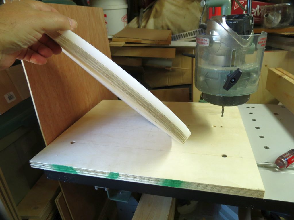
IMG_2902sc.jpg
IMG_2902sc.jpg (94.47 KiB) Viewed 9445 times
More to come.

Ed
{Knight of the Shopsmith} [Hero's don't wear capes, they wear dog tags]
User avatar
reible
Platinum Member
Posts: 11283
Joined: Thu Jul 20, 2006 12:08 pm
Location: Aurora, IL

Re: Fixture for my old OPR

Post by reible »

I debated here as to how I'd do the next step. I have modified my OPR to be able to use template guide bushings so I could do the next steps with the OPR but I think I'm the only person in the world with that capacity so I figured I'd go with a conventional plunge router set up. BTW I have a posting some where here with how to make your older OPR take template guide bushings if you are interested.

If you remember back a post or so the I drilled all the end hole of the arcs with a 3/8" bit. The reason for this is so I could use a 3/8" guide bushing in a plunge router to make the start and stop holes in the work piece.

The router setup looks like this:
IMG_2903sc.jpg
IMG_2903sc.jpg (97.02 KiB) Viewed 9437 times
Note the barrel of the guide bushing goes in the 3/8" hole and then you plunge the bit through the work piece. By having 3/8" hole for this means that all the hole that should be drilled can be but the pivot holes are only 1/4" so you will not mistakenly be able to drill those.
IMG_2904sc.jpg
IMG_2904sc.jpg (130.17 KiB) Viewed 9437 times
I number the holes so I could make sure I did them all, just went numerically. This too goes very fast.

When you flip it over the work piece looks like this:
IMG_2907sc.jpg
IMG_2907sc.jpg (87.75 KiB) Viewed 9437 times
We can now go back to the OPR and get ready to cut the slots. First you need to set the distance from the pivot hole to the pre-drilled ends of the arc. With the template hidden under the work piece you need to see the end points and that is why you add them. It also makes it easy to adjust the pivot to end point length. This is only set one time.

You pick out a hidden pivot point and then router end point to end point. Again it best to do in steps so you can maintain control.
IMG_2911msc.jpg
IMG_2911msc.jpg (58.85 KiB) Viewed 9437 times
You do them in order and when you are done you have the 4 short and 4 long arcs.

Now this fixture can be used to do inside or outside circles, arcs and the like. I'd not use it as is for smaller circles, you could make a larger circle and mount that so you have control of a smaller circle but again you have to have a way to maintain control.

Ed
{Knight of the Shopsmith} [Hero's don't wear capes, they wear dog tags]
Mike907
Platinum Member
Posts: 550
Joined: Fri Nov 09, 2012 2:02 am
Location: Anchorage, AK

Re: Fixture for my old OPR

Post by Mike907 »

Great tutorial, Ed, thanks!

Mike
User avatar
BuckeyeDennis
Platinum Member
Posts: 3815
Joined: Tue Jul 24, 2012 10:03 pm
Location: Central Ohio

Re: Fixture for my old OPR

Post by BuckeyeDennis »

It's very cool how you can make something that looks rather complex by using a fairly small number of simple steps. Once you had the process figured out, how long did it take you to make everything?

Now I'm wondering if it would make sense to make a lathe-mounted version with T-slots (instead of through slots) in the faceplate-side disc. That should be quite a lot more rigid. But do you think that the heads of T-bolts would slide freely enough?
User avatar
JPG
Platinum Member
Posts: 35600
Joined: Wed Dec 10, 2008 7:42 pm
Location: Lexington, Ky (TAMECAT territory)

Re: Fixture for my old OPR

Post by JPG »

BuckeyeDennis wrote:It's very cool how you can make something that looks rather complex by using a fairly small number of simple steps. Once you had the process figured out, how long did it take you to make everything?

Now I'm wondering if it would make sense to make a lathe-mounted version with T-slots (instead of through slots) in the faceplate-side disc. That should be quite a lot more rigid. But do you think that the heads of T-bolts would slide freely enough?
I am not sure what the hardware used is, but does not a carriage bolt suffice?

Not sure how a t slot would help.???
╔═══╗
╟JPG ╢
╚═══╝

Goldie(Bought New SN 377425)/4" jointer/6" beltsander/12" planer/stripsander/bandsaw/powerstation /Scroll saw/Jig saw /Craftsman 10" ras/Craftsman 6" thicknessplaner/ Dayton10"tablesaw(restoredfromneighborstrashpile)/ Mark VII restoration in 'progress'/ 10
E[/size](SN E3779) restoration in progress, a 510 on the back burner and a growing pile of items to be eventually returned to useful life. - aka Red Grange
User avatar
BuckeyeDennis
Platinum Member
Posts: 3815
Joined: Tue Jul 24, 2012 10:03 pm
Location: Central Ohio

Re: Fixture for my old OPR

Post by BuckeyeDennis »

JPG wrote:
BuckeyeDennis wrote:It's very cool how you can make something that looks rather complex by using a fairly small number of simple steps. Once you had the process figured out, how long did it take you to make everything?

Now I'm wondering if it would make sense to make a lathe-mounted version with T-slots (instead of through slots) in the faceplate-side disc. That should be quite a lot more rigid. But do you think that the heads of T-bolts would slide freely enough?
I am not sure what the hardware used is, but does not a carriage bolt suffice?

Not sure how a t slot would help.???
I made a jig with some routed T-slots in plywood recently, and also experimented with MDF. I found that a T-bolt head has more bearing surface that a carriage-bolt head, and so is less prone to deforming the material when tightened down. I also found that they slide more easily, with less tendency to "cock". Overall, the combination worked very well.

As for the advantage of a T-slot, those through-slots basically just leave "spokes" of material to support the disc, which would seem to reduce the axial stiffness considerably. A non-through slot would leave a web of solid material, which should make the disc considerably more rigid. But then again, with the slots running in opposite directions, the "sandwich" may be plenty stiff after the two opposing discs are clamped together.
Longworth.jpg
Longworth.jpg (85.93 KiB) Viewed 9377 times
User avatar
reible
Platinum Member
Posts: 11283
Joined: Thu Jul 20, 2006 12:08 pm
Location: Aurora, IL

Re: Fixture for my old OPR

Post by reible »

BuckeyeDennis wrote:It's very cool how you can make something that looks rather complex by using a fairly small number of simple steps. Once you had the process figured out, how long did it take you to make everything?

Now I'm wondering if it would make sense to make a lathe-mounted version with T-slots (instead of through slots) in the faceplate-side disc. That should be quite a lot more rigid. But do you think that the heads of T-bolts would slide freely enough?
Most projects as wood workers know are really a bunch of smaller steps. The key is to define the steps and work in a linear line to the end. A little planning goes a long way.

I did not time myself on the early part of the project but the cutting of the second disk and assembly took less then an hour including a massive amount of clean up........ little bits of plastic were flying about and I don't think I've come close to getting all of them yet. I was really interested in how the two parts would work together, almost seems like magic.

I was wondering about how rigid things were going to feel and I was happy with how things are. The boards are quite rigid to start with and the cuts did not seem to make much of a difference and when the two of them are put together, well they turn out to be very rigid. They are 1/2" thick so you have an inch of plastic when you are done. Sure if you stood on it it would flex but I can't see much happening when mounting a hollowed out bowl on it. Besides we are talking running the rpm way down, no more then 500 rpm I would think.

At this point I don't see any reason to look for other methods such as t-bolts/slots.

The hardware package I got has washers for the back side where the hex head bolt goes, then another washer below the gripper on the front side and another on top of the gripper. The wing nuts can be tightened enough to deform the grippers, bulging them helps hold the bowl. Since they are wing nuts your fingers limit how tight you get them pretty fast.

The question I have about the plastic is how flat they are after all of this. A hollowed out bowl is going to be reasonably light when you get to the point of finishing the bottom so I don't see strength being an issue. But if the bowl is wobbling about because things are not flat well that is an issue. This problem can be helped by how they would be mounted but again unless I get to the point of spinning them it is hard to guess how well it would work. Perhaps in the spring........

Ed
{Knight of the Shopsmith} [Hero's don't wear capes, they wear dog tags]
Post Reply