ecom1 wrote:beeg wrote:Or a piece of PVC pipe, with a slit in it. So ya can jusr slip it over the way tubes.
That works too - even easier!
Making a new stop ring (or buying one from Shopsmith) does not completely resolve the issue. You must first decide where in the table insert cutout you want the blade to be when you have the "table perfectly aligned". Do you want the left surface of the blade to be on the center line, or do you want the right surface to be on the center line. Or, maybe you want the center line to run right down the "center" of the blade?
There was a time when I said that what was most important was where Shopsmith intended it to be when the rig was designed. I won't say that anymore because Shopsmith will not declare a definitive position on where that should be.
I now position the table so that the center of my 1/8" setup disk from infinity is on that centerline. When I have it there, I secure the trunnion bolts and consider that table alignment complete.
I think that this sketch shows clearly why I think the way I do.
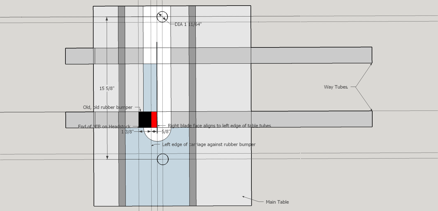
- The Cut Line and the Stop Ring on a 1991 Mark V Model 510.png (37.16 KiB) Viewed 5733 times
I have removed some dimensions from this drawing so as to not imply where that is dimensionally. That is dependent upon a number of key factors.
I loosen the trunnion bolts on the table and insert between the setup disk an either edge of the table cutout, a 1.444" +-.002"spacer. I then move the table to trap that spacer in location and tighten the trunnion bolts. The table is aligned. This means that the miter slots are parallel to the blade and the blade is located in the cutout where I want it.
Setup could not be simpler.
Side Comment: Note where the cutline is with respect to a line drawn between the table uprights (left side). This is center of rotation for the tilting table.