
Warning, this is advanced woodworking.
Part I
Many years ago I was working on a projects which required doing some drilling of items that were not easy to fixture for drilling and needed to be done with a fair amount of accuracy. I ended up having to eye ball each drilling operation and while my eye sight was good it still was very time consuming process. Add to that there were many of them and some holes were not though etc. this was a major effort. Sometime afterwards I came up with an idea which I have since used... but it has never been shared with anyone until few months ago. Previous designs were “as needed” but in this case I was interested in a more generic or platform type solution. The prototype will be described below.
My fear is that for most readers they are just going to think “he is a bit teched in the head” well that may be true but, try and read the whole posting anyway. You may never do this but maybe you will get some ideas from it. Oh yes DO TRY THIS AT HOME. On a personal note I'm getting really tired of the “don't try this a home” message they keep repeating all the time on TV.
The concept involved is very similar to the pin router idea. As you may know I have always like the concept of that and this might be thought of as an extension to the idea. In fact for those that own pin routers the router can be used for drilling as long as you use plunge bits and the hole sizes match bit sizes.
My solution was to make a simple piece that would fit on the shopsmith and provide a "pin" as a locating point. For now we can call this fixture the pin platform. A second piece or fixture is needed which is used with the pin to locate the hole and/or counter bore in the workpiece, more on that later.
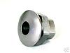
For the base unit I used a scrap of 3/4” plywood and started by finding a center line to work off of. It was not critical so I simply used a pencil after pushed the plywood against the way tubes and centering the plywood by eye. Two holes are needed that are align with the miter slots. The holes need to be flat bottomed and deep enough so the heads of the 1/4"-20 fasteners are not above the surface. The end result will be by using two sliding t-nuts you have an adjustable pin platform that can be locked in place.
[ATTACH]2795[/ATTACH]
[ATTACH]2796[/ATTACH]
At this point I needed to decide what I was going to use as a pin. I decided on the pins from the old OPR that I have. This might be something you do not have and may not want to use even if you do have it. You may also buy them from shopsmith if you want to it is the same pins they sell for the current OPR. (To be safe it would be nice to have a pin that can be drilled into and replaced as needed if you happen to drill to deep...) Well throwing caution to the wind I went with the inserts from the pin router. I know, I'm a wild a crazy guy.
What ever you pick for a pin you want to make sure that it allows you to re-center after the jig is taken off and then put back. In my case I did a couple of things I will detail. First the pins are taller then I like, I wish they were just short of a 1/4” high... in fact I decided to make them that high by counter boring a hole so that the pin was only above the platform surface by that almost 1/4”. This also means that I can use that counter bore hole and the bit that drilled it to help re-center the platform. How this works is the drill bit is mounted in the drill chuck then the platform is moved into position and located by feeding the bit into the hole (drill is not running). You can then lock the quill in the down position and that will hold the platform in place while you lock it with the sliding t-nuts.
[ATTACH]2797[/ATTACH]
[ATTACH]2798[/ATTACH]
In my case using the pin router pins I added a threaded insert so I can use any of the 1/4”, 3/8” or 1/2” pins. If you happen to have the router chuck for your shopsmith this also works for the alignment. For this you screw in the insert and mount the router chuck then using the quill feed you capture the pin with the chuck.
The counter bore also works or doesn't depending on how you view it as a place for the chips to collect when you are drilling but it will need to be cleaned out from time to time... you need to make sure the jig will sit flat and in contact with the platform and wood chips can be an issue.
That is about the extent of this version. I have a few improvements in mind for the next version.
Ed
Pin Drilling... advanced wood working 101
Moderator: admin
Pin Drilling... advanced wood working 101
- Attachments
-
- pinp1.jpg (116.85 KiB) Viewed 6217 times
-
- pinp2.jpg (119.41 KiB) Viewed 6218 times
-
- pinp3.jpg (79.51 KiB) Viewed 6218 times
-
- pinp4.jpg (72.04 KiB) Viewed 6217 times
{Knight of the Shopsmith} [Hero's don't wear capes, they wear dog tags]
Part II
As a quick review of the first posting, remember that we made a platform that has a pin that can be centered to the center line of the drill press. Having done that what ever is located by the pin will be drilled concentric with that. We also know that it is repeatable and is independent of drill bit size or type.
Now one needs to make a jig that takes advantage of the pin as a locater. That is the next part of the process and it turns out to be almost easy.
A few days ago I posted some pictures of a box I built to store table saw blades. I didn't go into the details of that design or how I made it. Since the drilling for the rivets were done using this concept and I took pictures I think it best to use this as an example. This part of the operation , or design is job specific so the best this can be is an example. So from my table saw blade storage project....
In my case I located places where I wanted to drill the holes for the rivets on one of the pieces. I took some care in the layout and marked the hole locations. Since the “drawer” is made up of a part (hardboard) that slides in the case and the top plywood part needs to be smaller to fit in and again I needed to keep things reasonable close. It also made since to drill both parts at the same time and to have the alignment of the top piece in relation to the lower done by the jig. When we get to the photos this will be clearly shown so I will not waste to many words on this part of the description.
This is an over view of what the jig looks like.
Fixture set to drill body hole followed by counter bore of plywood
[ATTACH]2799[/ATTACH]
Drawer ready to be drilled
[ATTACH]2800[/ATTACH]
The fixture again was a piece of scrap plywood. I used some trimmed off pine as stops because again that is what I had on hand. I started by attaching a length of the pine to an edge of the plywood with some small nails. From this I used a framing square to locate a side and put a strip of pine down. You need to leave some open area if you can so the wood chips and dust don't collect in an inside corner and mess up that as a location point. This would be the contact areas for the bottom hardboard piece. I used a couple more pieces of pine on top of the other pine along the side. The location of these pieces set the location of the “top” plywood piece. I added a second piece of pine to the very original pine strips so both the hardboard and the pine were located at the same points along an even edge.
Notice how hardboard is located then the off set required for the plywood is done by the second pine board
[ATTACH]2801[/ATTACH]
Aligned and ready to be drilled
[ATTACH]2802[/ATTACH]
With the fixture now complete to the point of being able to control the location of the two parts it was time to do some drilling. For this a small bit such as a 1/16” twist drill works well. Remove the pin from the platform and made sure the bit will not go to deep as to hit any part of the platform. Actually adjust the bit so it will drill through the drawer parts and into the fixture, you need not drill through the fixture. Drill the holes at the locations marked. If you have not done so before it is a good idea to somehow mark the drawer parts so you don't flip anything around after the drilling and if they get separated you can get them back together and aligned. What you have done at this point is to mark the hole locations on the fixture.
I have the option of using one of several pin sizes but for this project I went with a 1/4” pin so I used a 1/4” drill to enlarge the 1/16” starter holes put in above. A brad point bit does really well with this and gives a nice clean hole. After drilling the holes you can clean the edges of the holes on the bottom side where the pin will be going. What is really neat about what you just did is that you have now located the drill positions for each hole you are going to make. Even if you were a bit off in location due to not being centered 1/16” hole that will be taken care of in the following steps. Since you are drilling each hole through both parts at the same time they have to line up.... OK if you mess up putting the parts in the fixture then you can make a mess of things but don't do that!!
This is what the bottom of the fixture looks like with 6 1/4” holes for the pin to set in for drilling locations. Pin is located on platform below the jig
[ATTACH]2803[/ATTACH]
*************************************
more to come in my next post.
Ed
- Attachments
-
- pd1.jpg (137.36 KiB) Viewed 6213 times
-
- pd2.jpg (133.3 KiB) Viewed 6212 times
-
- pd3.jpg (114.26 KiB) Viewed 6214 times
-
- pd4.jpg (113.28 KiB) Viewed 6213 times
-
- pd5.jpg (106.05 KiB) Viewed 6214 times
{Knight of the Shopsmith} [Hero's don't wear capes, they wear dog tags]
The fixture is ready to use so install the pin in the platform and get the drill you want to use. In my case I think it was a 5/32” hole for the body of the rivet. Make sure you are set deep enough to drill through the two parts but not so deep as to hit the pin. Take the drawer that you used to mark the jig with and reposition it on the jig. Remember what I said about maybe messing up the hole locations a bit not being a big deal?? Well, this is why, you are now going to re-drill the holes! Bingo the holes are now in alignment to the fixture as will all the rest you drill.
Body hole 5/32" Note that pin in platform is locating the fixture for this drilling operation
[ATTACH]2804[/ATTACH]
So say you have 6 holes in every part and 18 parts, that makes 108 holes. Now if you took the time to mark each of the holes then hand aligned them and drilled them you will probably far exceed the time it took to make this platform and jig... and the platform is reusable and if you save the jig you can make more anytime you want. As you will see in the pictures you really need to write on the jig hole sizes etc if you are saving it. I know I could not remember drill sizes two years later so it was good they were written down.
Almost done now... In my case I did the drilling of body holes for a bunch of drawers then went on to change bits to a 1/4” Forester and set depth to have the rivet head below the surface. Again the bit was centered on the hole from before because of the pin location and fixture location. After doing all the plywood pieces it was time to do the hardboard. This becomes a problem because you can not simply flip the pieces over... what you have to do is locate them upside down so to speak. In my case I simply relocated the pine pieces to the same locations on the bottom of the jig, which then became the top of the jig and everything was once again in alignment after flipping the hardboard over. This might require you do a little extra thinking but that is what needs to happen to get it right...[hint notice dowel holes]
Body hole for rivet is now be redrilled to counter sink rivet head.
Again the pin in the platform along with the fixture are locating the hole.
[ATTACH]2805[/ATTACH]
After counter bore for rivet head is done
[ATTACH]2806[/ATTACH]
Comments, questions, bewilderment... do you want to see more stuff like this??? To easy?? to hard?? If I heard nothing then I will assume no one is interested in this sort of stuff and think to myself why am I wasting my time doing these posts? Oh yea it is because I like to amuse myself...
Ed
- Attachments
-
- pd6.jpg (137.42 KiB) Viewed 6211 times
-
- pd7.jpg (133.17 KiB) Viewed 6210 times
-
- pd8.jpg (126.85 KiB) Viewed 6205 times
{Knight of the Shopsmith} [Hero's don't wear capes, they wear dog tags]
-
dusty

- Platinum Member
- Posts: 21530
- Joined: Wed Nov 22, 2006 6:52 am
- Location: Tucson (Wildcat Country), Arizona
Pin Drilling
You are not wasting your time, Ed. This has been very informative. Even though I don't have any similar projects I do have some opportunities to utilize the basic method.
I appreciate the refresher too. I have seen some of this in a previous post by you but had forgotten about it. I won't forget this time.
Drilling accurate holes has always been a problem.
I'm thinking about a sort of indexing fixture. This approach will certainly help get some degree of accuracy built into it.
"Making Sawdust Safely"
Dusty
Sent from my Dell XPS using Firefox.
Dusty
Sent from my Dell XPS using Firefox.
-
a1gutterman

- Platinum Member
- Posts: 3653
- Joined: Tue Jan 09, 2007 12:45 am
- Location: "close to" Seattle
Oakay Ed, I followed that pretty good, I think. But I am stumped as to exactly how you are using the pin in the platform to line up the jig holding the work pieces. I think that you are using the six holes that you drilled in the jig to place them, one at a time over the pin, but then I get lost on how that locates the location to drill the hole through the work piece. I hope that I am not too dense here, and that you do knot loose patience explaining what must seem obvious to some...
BTW, I enjoy these posts, even if it takes me awhile to figure them out. The pictures are VERY helpful. I am the kind of guy that learns fastest when showed how rather then told how.
BTW, I enjoy these posts, even if it takes me awhile to figure them out. The pictures are VERY helpful. I am the kind of guy that learns fastest when showed how rather then told how.
Tim
Buying US made products will help keep YOUR job or retirement funds safer.
Buying US made products will help keep YOUR job or retirement funds safer.
-
easterngray
- Platinum Member
- Posts: 720
- Joined: Sun Mar 11, 2007 8:28 pm
- Location: Cape Cod MA.
Great Stuff!
I think this is great stuff Ed. Thanks for your efforts in sharing this with us! Alec
1960 Aniversary Model Mark 5 500 "Goldie" with most SPT's
Hi Dusty,
As it happens I have plans for an indexing fixture. I ran out of money before I could get to it this past year but it is in the 2009 budget. It all starts with getting a indexing part which I hope to order within the next few months. I thinking I'm better off getting one that should be right on or very close then using it to make several more for various projects I have planned. To make the one in to many I want to have my fixture done and use that. Sound like fun. Keep us posted on your ideas.
Ed
dusty wrote:You are not wasting your time, Ed. This has been very informative. Even though I don't have any similar projects I do have some opportunities to utilize the basic method.
I appreciate the refresher too. I have seen some of this in a previous post by you but had forgotten about it. I won't forget this time.
Drilling accurate holes has always been a problem.
I'm thinking about a sort of indexing fixture. This approach will certainly help get some degree of accuracy built into it.
{Knight of the Shopsmith} [Hero's don't wear capes, they wear dog tags]
Hi Tim,
The first time I do this I use a marked model to determine the location of the holes. By drilling a small 1/16" hole through the marked work piece and the fixture I determine the places to drill the fixture.
Depending on the pin size I then drill the fixture at those locations. Keeping in mind that drilling or routing are radial operations (unlike using a table saw which is linear) the only thing that counts is the center location. The fixture then needs only to locate by that center location. With the pin in place and aligned to the center line of the drill the fixture is then located. The parts are located on the fixture so the holes are then lined up to drill.
By making the fixture first and locating the parts on the fixture and then doing the drilling of the starter holes makes this all the better. Sure you have to mark and drill the one set of hole but the rest are located for you by putting the fixture over the pin... and the fixture can be at any angle to the table...
Did that help? If not ask again because I'm sure if it wasn't clear to you then it wasn't clear to others either.
Ed
a1gutterman wrote:Oakay Ed, I followed that pretty good, I think. But I am stumped as to exactly how you are using the pin in the platform to line up the jig holding the work pieces. I think that you are using the six holes that you drilled in the jig to place them, one at a time over the pin, but then I get lost on how that locates the location to drill the hole through the work piece. I hope that I am not too dense here, and that you do knot loose patience explaining what must seem obvious to some...
BTW, I enjoy these posts, even if it takes me awhile to figure them out. The pictures are VERY helpful. I am the kind of guy that learns fastest when showed how rather then told how.
{Knight of the Shopsmith} [Hero's don't wear capes, they wear dog tags]
-
a1gutterman
- Platinum Member
- Posts: 3653
- Joined: Tue Jan 09, 2007 12:45 am
- Location: "close to" Seattle
Hey! Maybe I understand after all: The pin is holding the jig in place, and with the work piece in place on the jig, you are drilling straight down toward the pin, but knot deep enough to actually hit the pin. Is that right?reible wrote:Hi Tim,
The first time I do this I use a marked model to determine the location of the holes. By drilling a small 1/16" hole through the marked work piece and the fixture I determine the places to drill the fixture.
Depending on the pin size I then drill the fixture at those locations. Keeping in mind that drilling or routing are radial operations (unlike using a table saw which is linear) the only thing that counts is the center location. The fixture then needs only to locate by that center location. With the pin in place and aligned to the center line of the drill the fixture is then located. The parts are located on the fixture so the holes are then lined up to drill.
By making the fixture first and locating the parts on the fixture and then doing the drilling of the starter holes makes this all the better. Sure you have to mark and drill the one set of hole but the rest are located for you by putting the fixture over the pin... and the fixture can be at any angle to the table...
Did that help? If not ask again because I'm sure if it wasn't clear to you then it wasn't clear to others either.
Ed
Tim
Buying US made products will help keep YOUR job or retirement funds safer.
Buying US made products will help keep YOUR job or retirement funds safer.
You got it!
Ed
Ed
a1gutterman wrote:Hey! Maybe I understand after all: The pin is holding the jig in place, and with the work piece in place on the jig, you are drilling straight down toward the pin, but knot deep enough to actually hit the pin. Is that right?
{Knight of the Shopsmith} [Hero's don't wear capes, they wear dog tags]