Page 1 of 3
motor mark vii
Posted: Wed Jan 27, 2016 10:56 am
by hobbies
I just got a mark vii didnt have a switch but found one when i hook it up all the motor does is hums i wireed around the switch same thing i got a new compasstor same whats else do i need to check
Re: motor mark vii
Posted: Wed Jan 27, 2016 3:50 pm
by JPG
hobbies wrote:I just got a mark vii didnt have a switch but found one when i hook it up all the motor does is hums i wireed around the switch same thing i got a new compasstor same whats else do i need to check
The original switch included directional switching for the start circuit.
Which motor do you have? Or, what are the wire colors? 6 wires or 8 wires and does it also have a start relay?
Re: motor mark vii
Posted: Thu Jan 28, 2016 12:09 pm
by hobbies
six wires no dont think so on starter relay
Re: motor mark vii
Posted: Thu Jan 28, 2016 12:11 pm
by hobbies
yellow,red,black,white,
Re: motor mark vii
Posted: Thu Jan 28, 2016 12:25 pm
by JPG
I believe you have an A. O. Smith motor.
Assuming so:
Connect red wire to yellow wire.
Connect red/tracer wire to capacitor.
Connect black/tracer to other terminal on capacitor.
Connect white power to white motor wire.
Connect black power to black motor wire.
To reverse direction, reverse red and red/tracer wires.
Re: motor mark vii
Posted: Sun Jan 31, 2016 1:13 am
by everettdavis
I am working to build out a D size illustrated parts diagram for the 1960's Mark VII (similar to those I did for the Mark V), but while that is in the works, see if this Mark VII Electrical Connections to Motor diagram I am re-doing will help you any.
Everett
Re: motor mark vii
Posted: Sun Jan 31, 2016 1:37 am
by JPG
[font=][font=][/font][/font]
everettdavis wrote:I am working to build out a D size illustrated parts diagram for the 1960's Mark VII (similar to those I did for the Mark V), but while that is in the works, see if this Mark VII Electrical Connections to Motor diagram I am re-doing will help you any.
Everett
Mark VII Electrical Connections to Motor.pdf
AH OH!!!!
Double check those drawings. Both have errors!
Also there is another A O Smith motor that uses an external relay.
Re: motor mark vii
Posted: Mon Feb 01, 2016 10:06 am
by everettdavis
JPG wrote:[font=][font=][/font][/font]
everettdavis wrote:I am working to build out a D size illustrated parts diagram for the 1960's Mark VII (similar to those I did for the Mark V), but while that is in the works, see if this Mark VII Electrical Connections to Motor diagram I am re-doing will help you any.
Everett
The attachment Mark VII Electrical Connections to Motor.pdf is no longer available
AH OH!!!!
Double check those drawings. Both have errors!
Also there is another A O Smith motor that uses an external relay.
Can you elaborate just a bit on the error? The redone drawing came from the OEM manual PDF you emailed me relative to post
http://www.shopsmith.com/ss_forum/viewt ... 93#p202493
If I understand, you are saying the Magna American OEM manual wiring diagrams were wrong?
The only thing I did 'extra' was on Terminal 5 (which has a jumper 501596) was to extend the color to show the potential on the Yellow or Purple wires on the jumper connection.
I have attached a side by side to show what I did from the OEM manual. My eyes aren't what they once were, so I could have missed something.
Also if you have a drawing on the 3rd motor type with the external relay, I will strive to add one like this for it.
Since I have no physical Mark VII to reference (and apparently I would need three), it is a more difficult task to re-do a manual of this model, but I feel it is something that once vetted for accuracy, can be of benefit to others who have or acquire 1960 vintage Mark VII's. Lord knows so many of you have contributed to my knowledge.
I look forward to seeing what errors are there and correcting them.
Everett
Update: As I look at it, since Magna didn't specify the specific core color of the tracer wire, I listed it as Red Tracer etc. and drew it Red Some may not know that a tracer is an added color to help identify a specific wire in a bundle, often has higher heat resistance, and may be a cloth based insulation with a tracer color as illustrated in the photo below.
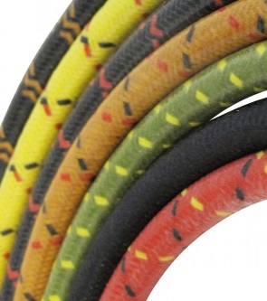
- Wire with tracer colors.jpg (33.83 KiB) Viewed 5480 times
Re: motor mark vii
Posted: Mon Feb 01, 2016 9:09 pm
by JPG
You did not get the manual input correctly. The error is around the 'internal start switch', the capacitor leads and the 'L1' black wire.
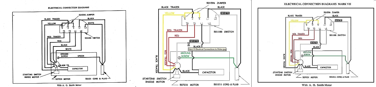
- ClipboardMARK VII MOTOR AOSMITH MAN-FIRST-CURRENT.jpg (143.55 KiB) Viewed 5467 times
The manual drawing is left, your first post center and your last post right.
Will follow with the ge and the third version.
The tracer wires are white with a tracer the color identified.
Kudos on the added color. A dashed line could represent the 'x' tracer wires.
Re: motor mark vii
Posted: Mon Feb 01, 2016 9:32 pm
by BuckeyeDennis
JPG wrote:You did not get the manual input correctly. The error is around the 'internal start switch', the capacitor leads and the 'L1' black wire.
ClipboardMARK VII MOTOR AOSMITH MAN-FIRST-CURRENT.jpg
The manual drawing is left, your first post center and your last post right.
Will follow with the ge and the third version.
The tracer wires are white with a tracer the color identified.
Kudos on the added color. A dashed line could represent the 'x' tracer wires.
Aha! I also couldn't find an error in Everett's drawings earlier. I see now that there are two different versions of the "original" 507231 drawing floating around. Compare to the one in Everett's "side-by-side" PDF above.