Merry Christmas and Happy New Year to everyone! Happy Chinese New Year tomorrow!
Finally getting back into the VII and it will be brief as I have some Covid related procedures that will take me out of commission for most of February. Will be back and running full speed after that.
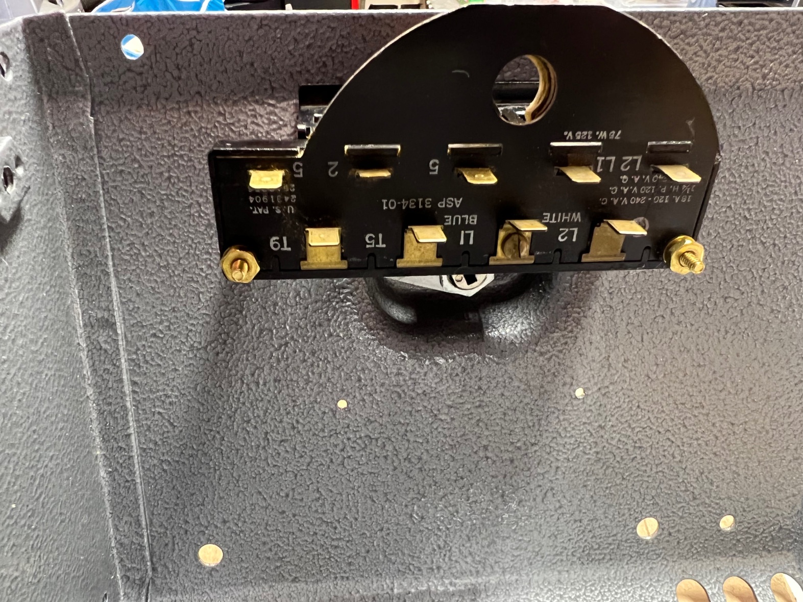
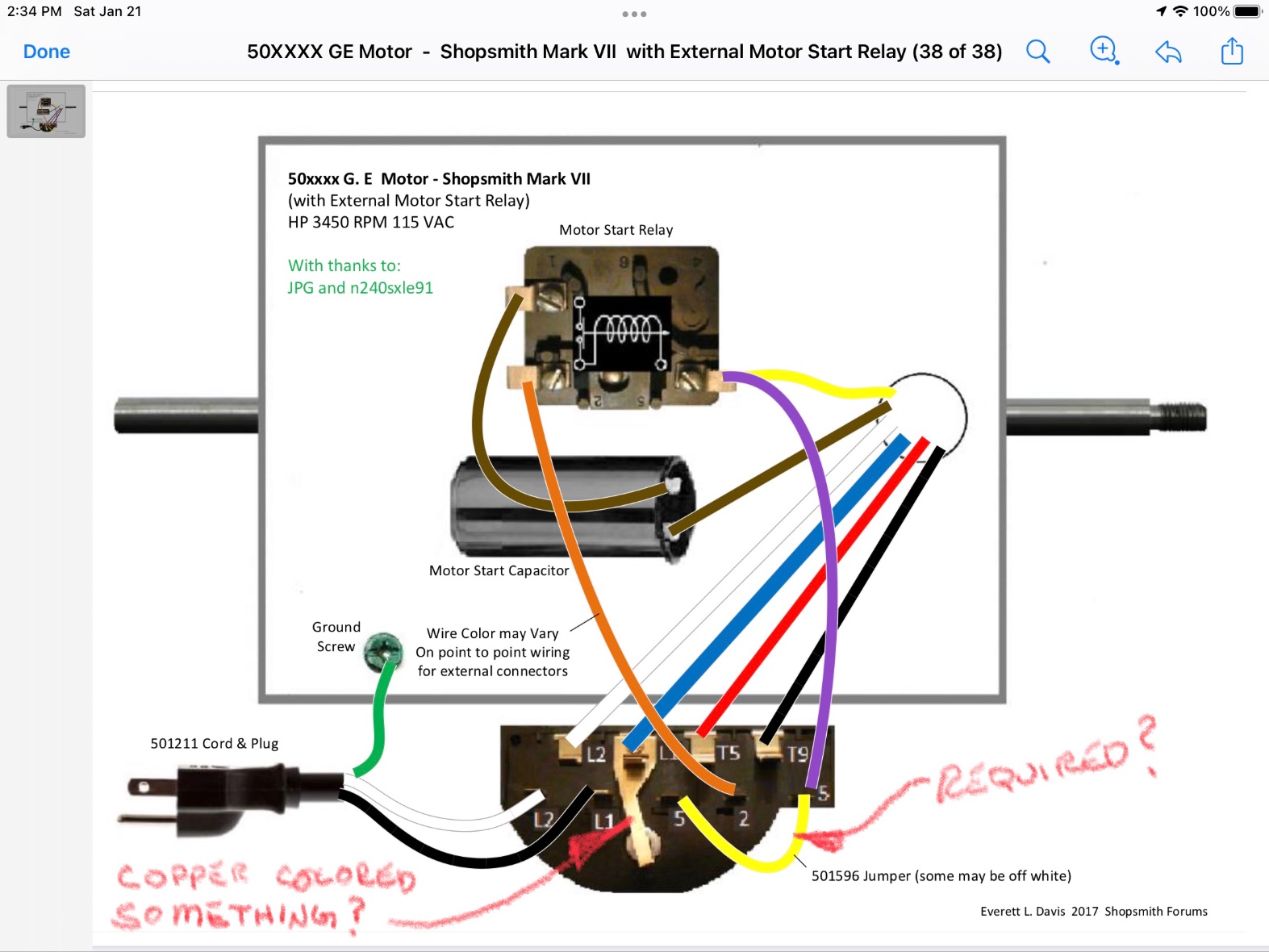
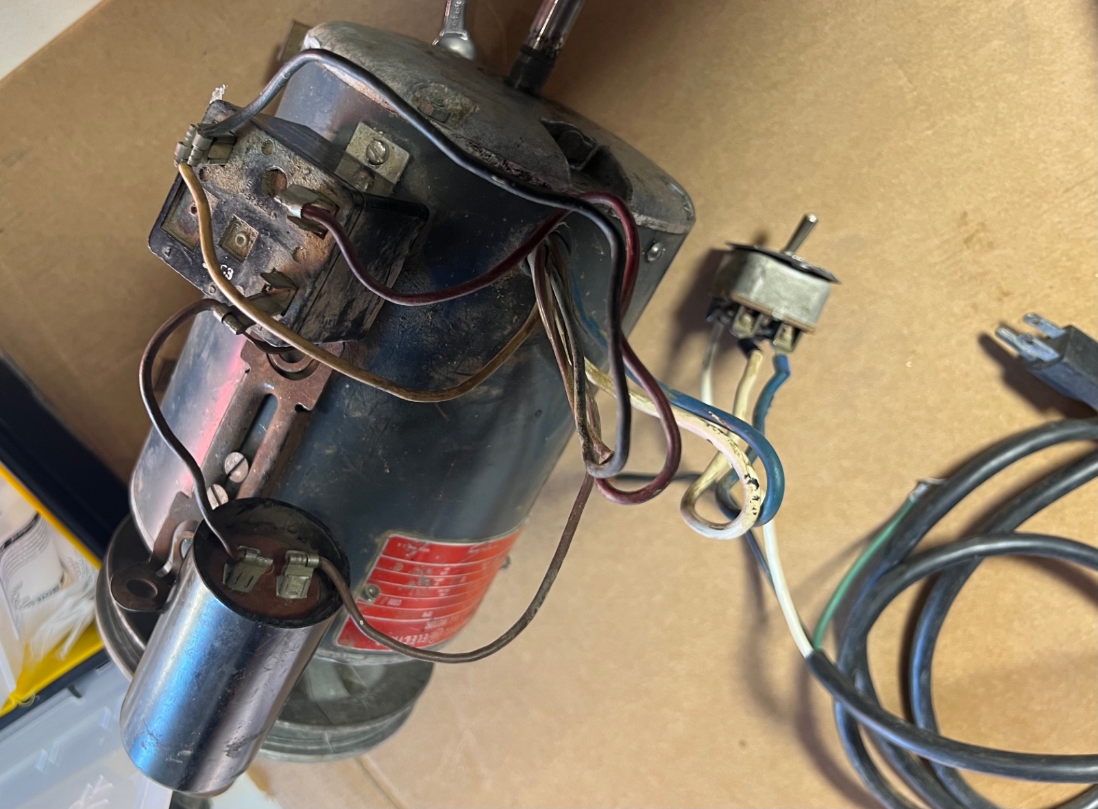
Anyway, starting on the assembly, bearings are all replaced and next on the list is electrical. Once again I want to thank JPG for all the information. Electrical is my greatest weakness when working on old equipment. So here are some pics of what I have and the electrical drawing that I’m pretty sure I should follow. It’s a GE motor with a relay and capacitor. It was rewired for just a switch and I would like to use the original reverse/stop/forward switch.
At present the motor was rebuilt and runs great and I don’t want to screw up the wiring so that it doesn’t do that anymore.
So, if I cut wires, add terminals and hook up per electrical drawing will all function as planned?
I’m guessing I need to add yellow jumper?
I’m not sure what the copper “y” shaped thing is or does that is next to the blue wire? A jumper?
It’s dirty but will be cleaned up before install.
Thank you Miken cam works beautifully!
Thank you for any and all assistance or even any and all critiquing.