I preface this with the disclosure that this post does not describe the adjustments themselves, but rather a way to determine what adjustments are needed and shows a method to check the results(or need for adjusting).
The pix that follow are of the same machine shown earlier in this thread and it is not altered from when those earlier pix were taken.
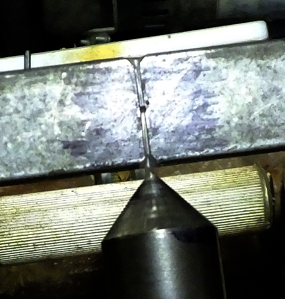
The first pix shows the 'pointer' relative to the 'gauge' used earlier, but was taken just before the following was performed.
- TILT GAUGE.jpg (766.79 KiB) Viewed 2088 times
First a word about the 'accuracy' inherent in this procedure. The distance from the right aux table to the left aux table is approximately 50". A deviation of .05"(slightly less than 1/16") represents an angle difference of 0.0573 degrees. That angle will also result in a .004" slope over a 4" width.
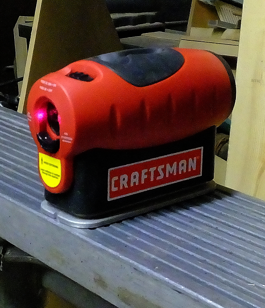
The laser used here was merely placed upon the narrow M5 aux table approximately centered between the aux table mounting posts. No effort was made to position it precisely, but when moved around, little or no effect was observed when moving it.
- LASER SOURCE - POSITION.jpg (902.04 KiB) Viewed 2088 times
It was operated in the mode where a horizontal line is projected. That line will be parallel to the aux table top plane(at least the top surface directly under the laser).
OK so now we are projecting a line towards the left end that is essentially parallel to the aux table front to rear). It remains to be determined if the projection tilts up/down from the right side to the left side due to tilt in the aux table.
Of interest to us is whether the aux table top is parallel to the way tubes end to end.
So we need a way to determine that.
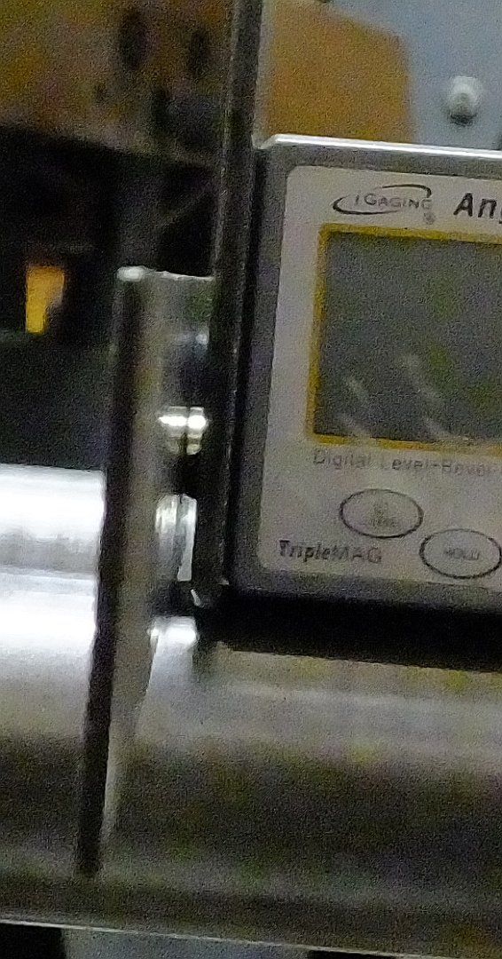
I used two carpenter's framing squares as a method to determine the projected height of the laser beam above the way tubes at the far left end and at a point close to the right end(close to the laser). The tongue of both squares was placed across the way tubes(front to rear) with the body of one over the front way tube and the body of the second square over the rear way tube. The squares were held to each other by magnets and the pair was held vertical by using an i-gauge that has magnets on three of the four sides of the square body. The i-gauge was not turned on, but was merely used as a holding device.
- SQUARE SUPPORT.jpg (471.98 KiB) Viewed 2088 times
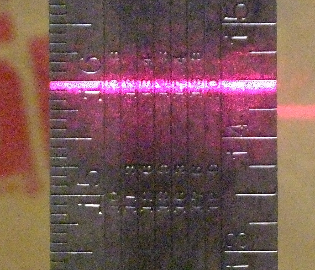
The aux table was moved up to approximately where the projected line crossed the squares at 16" above the way tubes as indicated on the squares. This height is greater than the maximum height of the main table attainable and was chosen arbitrarily.
The projected line is shown in the next two pix.
- LEFT FRONT WAY TUBE HEIGHT.jpg (1.08 MiB) Viewed 2088 times
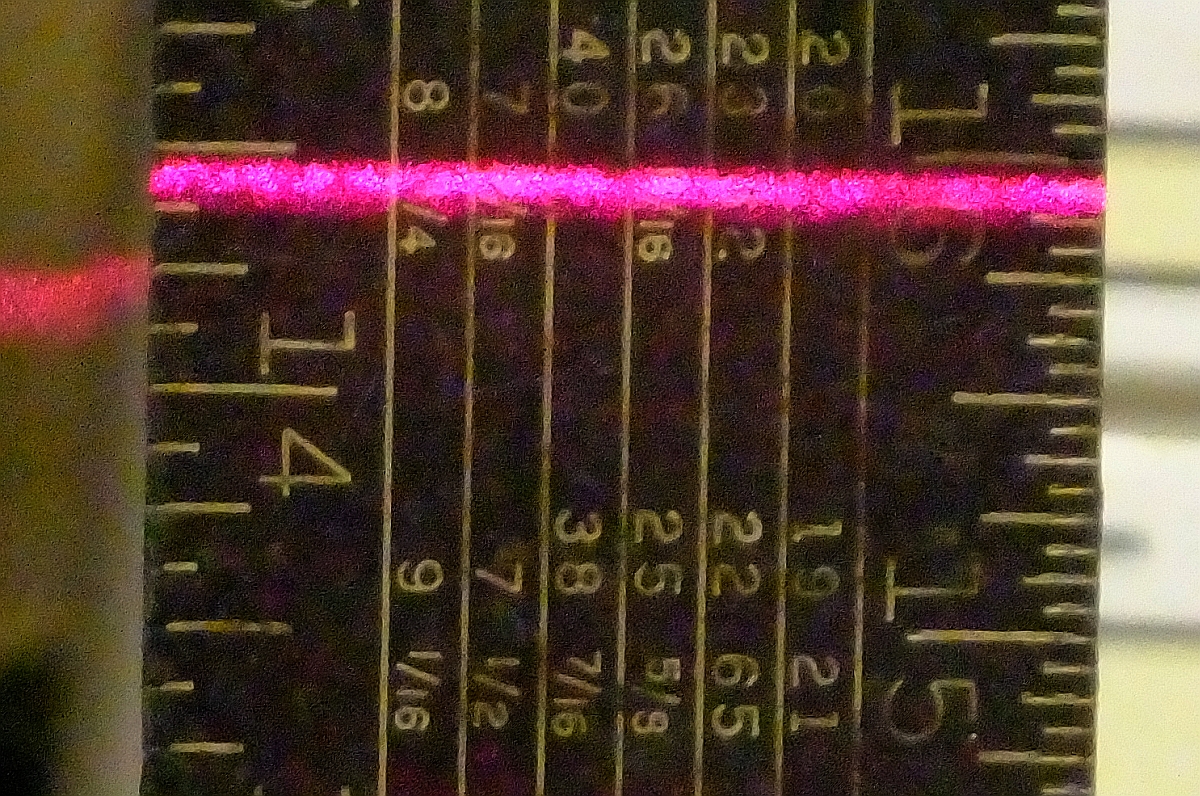
- LEFT REAR WAY TUBE HEIGHT.jpg (882.66 KiB) Viewed 2088 times
Notice the rear is less than 1/32" lower than the front. That represents less than a 0.2 degree tilt downwards towards the rear.
So now the squares were moved close to the right end.
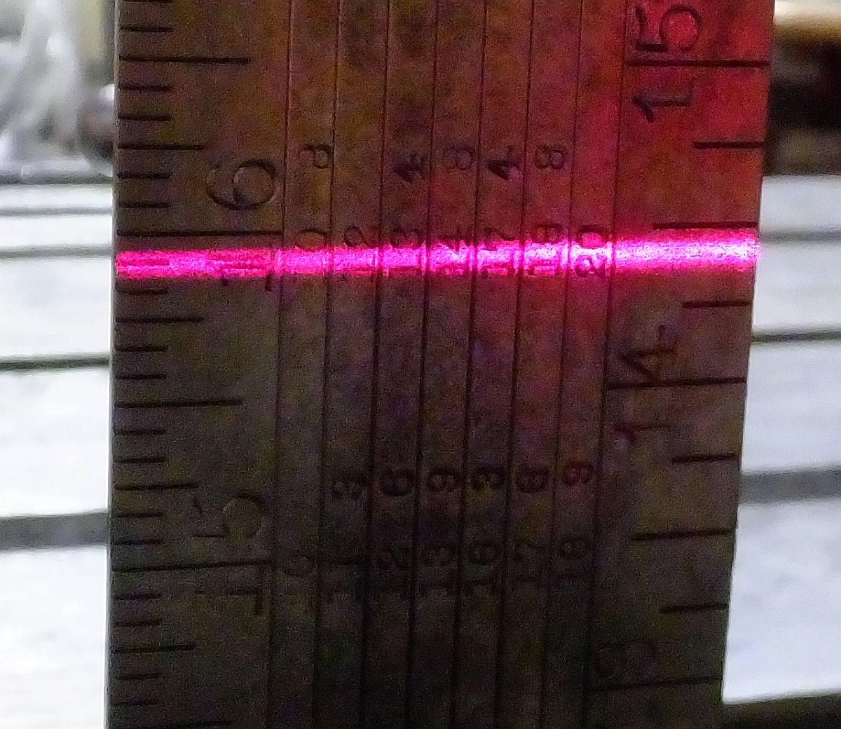
- RIGHT FRONT WAY TUBE HEIGHT.jpg (984.76 KiB) Viewed 2088 times
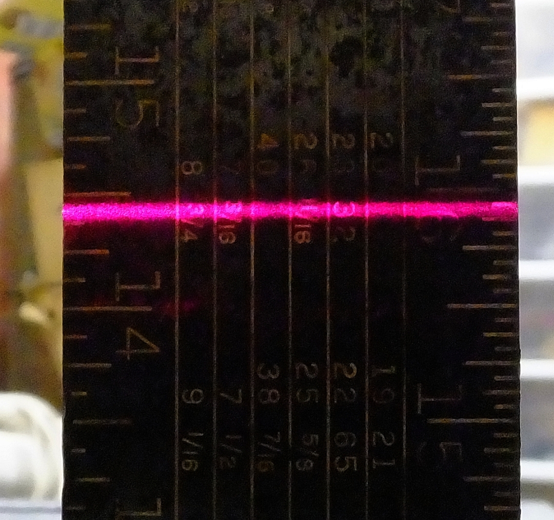
- RIGHT REAR WAY TUBE HEIGHT.jpg (751.12 KiB) Viewed 2088 times
Both front and rear are about 1/32" lower than at the left end. That amounts to about .034 degrees. ( a word of caution re the scale on the front square. It is calibrated in 1/12", not 1/16")
Now we still do not know the situation with the aux table, but that has to wait until after the main table is aligned. Then the aux table can be adjusted to it. Keep in mind the laser is not moved throughout this entire procedure so the front/rear difference observed may be due to slight aux table tilt downwards towards the rear.
However since the front/rear deviation is the
same at both the close and far end, we can conclude that it is indeed the table that is tilted, and not the way tubes being twisted. That confirms the correctness of the previous set screw adjustment.
Furthermore since the beam is lower at the right position than at the left end, we can conclude the aux table is slightly tilted with the inside edge higher than the outside edge. Again the difference is about 1/32" and indicates an error angle of about 0.034 degrees which results in the left side of the table being about 0.002" lower than at the right side.
The next post checks the main table.


