Aligning BASE

Forum for Maintenance and Repair topics. Feel free to ask questions or contribute.

Moderator: admin

User avatar
JPG
Platinum Member
Posts: 35598
Joined: Wed Dec 10, 2008 7:42 pm
Location: Lexington, Ky (TAMECAT territory)

Re: Aligning BASE

Post by JPG »

I question whether the rails/tubes are stout enough to overcome the table mounts not being close to correct.

Not having those rails on the Mark 5, requires the table to mount adjustment be done without them.


Now FWIW if one is relying on the rails/tubes to achieve alignment, the table/mount nuts could be left loose. ;)

That would be a different way to achieve left/right compatibility. :rolleyes:
╔═══╗
╟JPG ╢
╚═══╝

Goldie(Bought New SN 377425)/4" jointer/6" beltsander/12" planer/stripsander/bandsaw/powerstation /Scroll saw/Jig saw /Craftsman 10" ras/Craftsman 6" thicknessplaner/ Dayton10"tablesaw(restoredfromneighborstrashpile)/ Mark VII restoration in 'progress'/ 10
E[/size](SN E3779) restoration in progress, a 510 on the back burner and a growing pile of items to be eventually returned to useful life. - aka Red Grange
User avatar
JPG
Platinum Member
Posts: 35598
Joined: Wed Dec 10, 2008 7:42 pm
Location: Lexington, Ky (TAMECAT territory)

Re: Aligning BASE

Post by JPG »

As an added observation, I shoved a 3/4" board under one leg 'foot'.

That created a teeter-totter effect.

I checked to see if that introduced any 'twist' to the way tubes.

It did not!


So I conclude floor flatness is a non-issue as long as the teetering is acceptable.
╔═══╗
╟JPG ╢
╚═══╝

Goldie(Bought New SN 377425)/4" jointer/6" beltsander/12" planer/stripsander/bandsaw/powerstation /Scroll saw/Jig saw /Craftsman 10" ras/Craftsman 6" thicknessplaner/ Dayton10"tablesaw(restoredfromneighborstrashpile)/ Mark VII restoration in 'progress'/ 10
E[/size](SN E3779) restoration in progress, a 510 on the back burner and a growing pile of items to be eventually returned to useful life. - aka Red Grange
User avatar
JPG
Platinum Member
Posts: 35598
Joined: Wed Dec 10, 2008 7:42 pm
Location: Lexington, Ky (TAMECAT territory)

Using a laser level to align base and table.

Post by JPG »

I preface this with the disclosure that this post does not describe the adjustments themselves, but rather a way to determine what adjustments are needed and shows a method to check the results(or need for adjusting).

The pix that follow are of the same machine shown earlier in this thread and it is not altered from when those earlier pix were taken.

The first pix shows the 'pointer' relative to the 'gauge' used earlier, but was taken just before the following was performed.
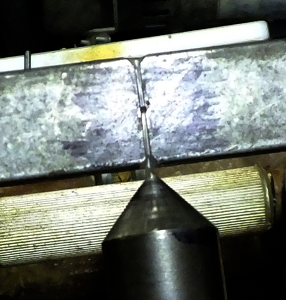
TILT GAUGE.jpg
TILT GAUGE.jpg (766.79 KiB) Viewed 2091 times
First a word about the 'accuracy' inherent in this procedure. The distance from the right aux table to the left aux table is approximately 50". A deviation of .05"(slightly less than 1/16") represents an angle difference of 0.0573 degrees. That angle will also result in a .004" slope over a 4" width.

The laser used here was merely placed upon the narrow M5 aux table approximately centered between the aux table mounting posts. No effort was made to position it precisely, but when moved around, little or no effect was observed when moving it.
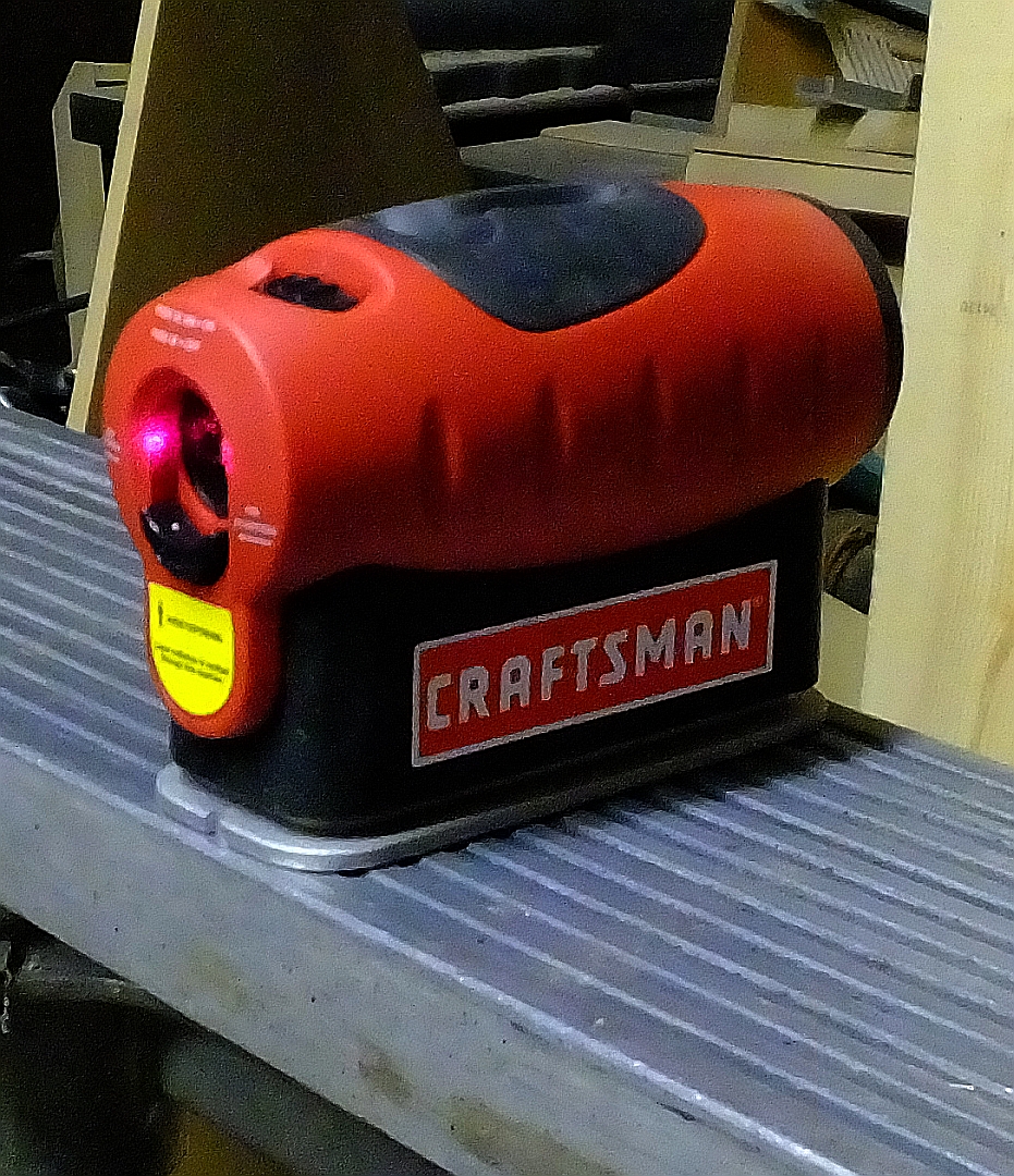
LASER SOURCE - POSITION.jpg
LASER SOURCE - POSITION.jpg (902.04 KiB) Viewed 2091 times
It was operated in the mode where a horizontal line is projected. That line will be parallel to the aux table top plane(at least the top surface directly under the laser).

OK so now we are projecting a line towards the left end that is essentially parallel to the aux table front to rear). It remains to be determined if the projection tilts up/down from the right side to the left side due to tilt in the aux table.

Of interest to us is whether the aux table top is parallel to the way tubes end to end.

So we need a way to determine that.

I used two carpenter's framing squares as a method to determine the projected height of the laser beam above the way tubes at the far left end and at a point close to the right end(close to the laser). The tongue of both squares was placed across the way tubes(front to rear) with the body of one over the front way tube and the body of the second square over the rear way tube. The squares were held to each other by magnets and the pair was held vertical by using an i-gauge that has magnets on three of the four sides of the square body. The i-gauge was not turned on, but was merely used as a holding device.
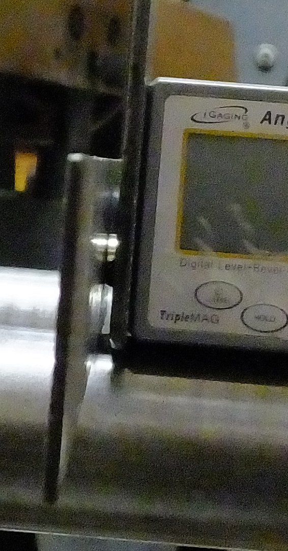
SQUARE SUPPORT.jpg
SQUARE SUPPORT.jpg (471.98 KiB) Viewed 2091 times
The aux table was moved up to approximately where the projected line crossed the squares at 16" above the way tubes as indicated on the squares. This height is greater than the maximum height of the main table attainable and was chosen arbitrarily.

The projected line is shown in the next two pix.
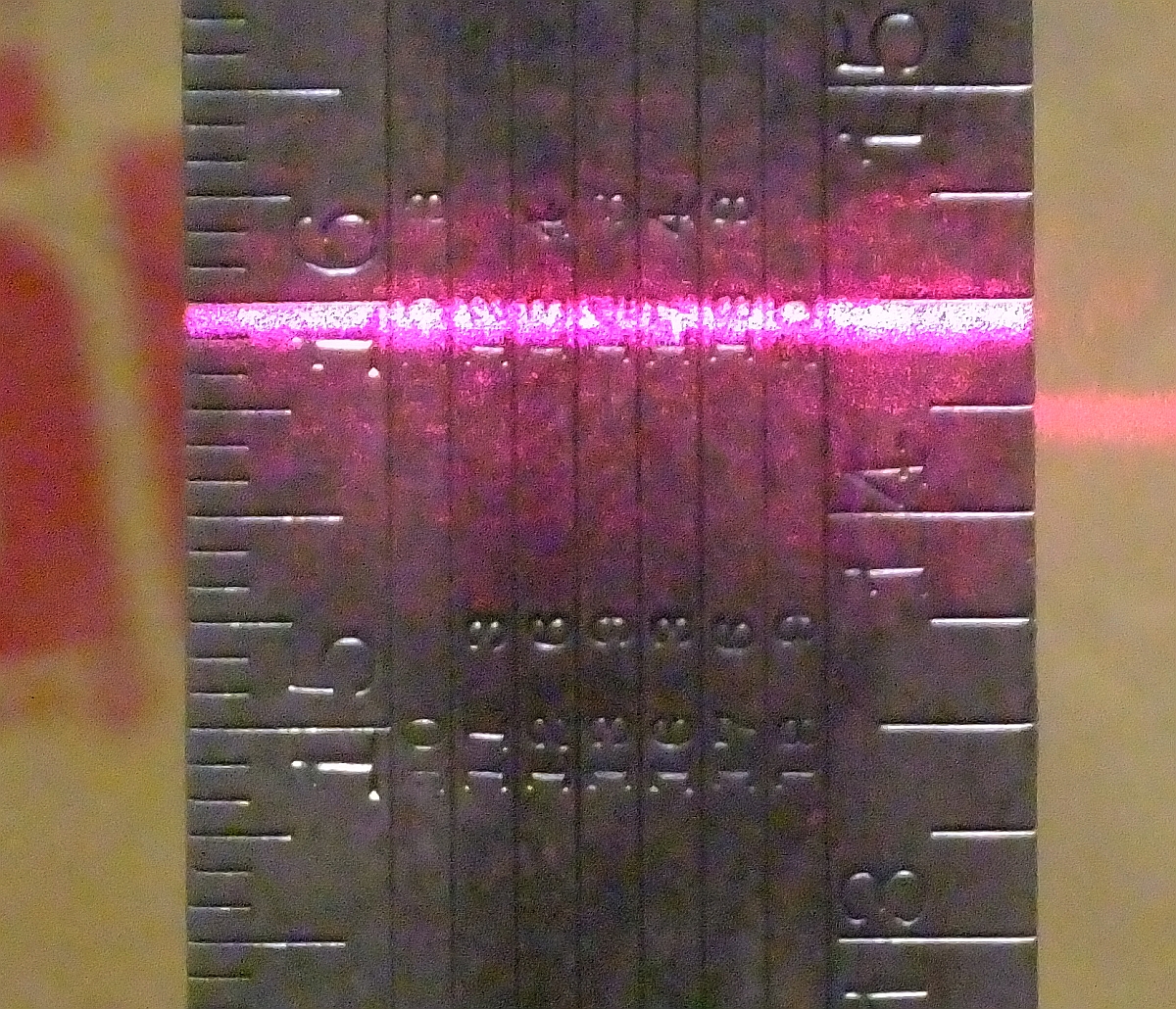
LEFT FRONT WAY TUBE HEIGHT.jpg
LEFT FRONT WAY TUBE HEIGHT.jpg (1.08 MiB) Viewed 2091 times
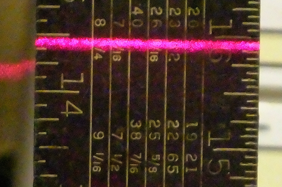
LEFT REAR WAY TUBE HEIGHT.jpg
LEFT REAR WAY TUBE HEIGHT.jpg (882.66 KiB) Viewed 2091 times

Notice the rear is less than 1/32" lower than the front. That represents less than a 0.2 degree tilt downwards towards the rear.


So now the squares were moved close to the right end.
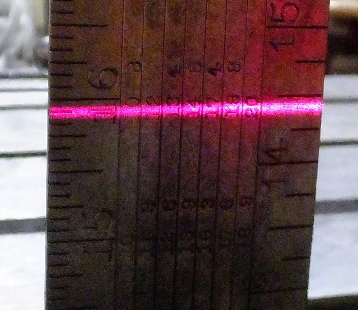
RIGHT FRONT WAY TUBE HEIGHT.jpg
RIGHT FRONT WAY TUBE HEIGHT.jpg (984.76 KiB) Viewed 2091 times
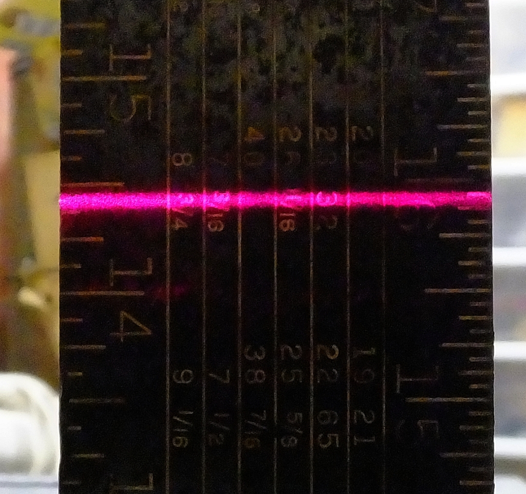
RIGHT REAR WAY TUBE HEIGHT.jpg
RIGHT REAR WAY TUBE HEIGHT.jpg (751.12 KiB) Viewed 2091 times
Both front and rear are about 1/32" lower than at the left end. That amounts to about .034 degrees. ( a word of caution re the scale on the front square. It is calibrated in 1/12", not 1/16")

Now we still do not know the situation with the aux table, but that has to wait until after the main table is aligned. Then the aux table can be adjusted to it. Keep in mind the laser is not moved throughout this entire procedure so the front/rear difference observed may be due to slight aux table tilt downwards towards the rear.

However since the front/rear deviation is the same at both the close and far end, we can conclude that it is indeed the table that is tilted, and not the way tubes being twisted. That confirms the correctness of the previous set screw adjustment.

Furthermore since the beam is lower at the right position than at the left end, we can conclude the aux table is slightly tilted with the inside edge higher than the outside edge. Again the difference is about 1/32" and indicates an error angle of about 0.034 degrees which results in the left side of the table being about 0.002" lower than at the right side.

The next post checks the main table.
╔═══╗
╟JPG ╢
╚═══╝

Goldie(Bought New SN 377425)/4" jointer/6" beltsander/12" planer/stripsander/bandsaw/powerstation /Scroll saw/Jig saw /Craftsman 10" ras/Craftsman 6" thicknessplaner/ Dayton10"tablesaw(restoredfromneighborstrashpile)/ Mark VII restoration in 'progress'/ 10
E[/size](SN E3779) restoration in progress, a 510 on the back burner and a growing pile of items to be eventually returned to useful life. - aka Red Grange
User avatar
dusty
Platinum Member
Posts: 21530
Joined: Wed Nov 22, 2006 6:52 am
Location: Tucson (Wildcat Country), Arizona

Re: Aligning BASE

Post by dusty »

I'm having some difficulty concurring with your mathematical conclusions but I get the drift (I think).

So far you have established a reference (your right hand extension table) against which the main table will be compared. That reference is basically a horizontal plane located 16" above and parallel to the plane of the Way Tubes.

Please clarify: What are you going to be checking against this beam. The gest of this problem is the relative height of the left and right sides of the three tables (main table tilt, left extension table, right extension table). When perfectly aligned, all three should be in the same plane and that plane should be parallel to the plane formed by the Way Tubes.

Please do correct me if I have gotten this wrong.
"Making Sawdust Safely"
Dusty
Sent from my Dell XPS using Firefox.
User avatar
dusty
Platinum Member
Posts: 21530
Joined: Wed Nov 22, 2006 6:52 am
Location: Tucson (Wildcat Country), Arizona

Re: Aligning BASE

Post by dusty »

Does the laser level switch accuarately from horizontal o vertical. Does the spec sheet give any numbers?

I'm thinking that if it does you could simply calibrate the level against the plane established by the vertical support legs and then switch to horizontal to check the tilt.

PS No need to respond. I'll check the manual.
http://www.manualslib.com/manual/497384 ... e=2#manual
"Making Sawdust Safely"
Dusty
Sent from my Dell XPS using Firefox.
User avatar
JPG
Platinum Member
Posts: 35598
Joined: Wed Dec 10, 2008 7:42 pm
Location: Lexington, Ky (TAMECAT territory)

Re: Aligning BASE

Post by JPG »

I stopped this post after the forum software choked when I 'submitted' it. I am thankful it will not require doing it over.

The next post was to be an illustration of the main table 'measurements' and will be done shortly.

The following should be added to the initial laser post, but I fear doing anything with it after last night's issue(Thank you Admin for salvaging it).

As mentioned at the top, I am not describing actual adjustments, but presenting a method for evaluating alignment.


What I have established is that plane parallel to the way tubes. If the 'measurements' indicated the plane(as projected by the laser beam) was 'off' parallel, adjustments would be needed. Possible adjustments would be:

Set screw to remove any way tube twist first.

Then aux table to correct both front rear tilt and left right tilt.

I need to mention that the aux table can be 'wiggled' slightly and that affects the location of the projected beam at the other end significantly. Therefore a 'nominal' mid position of the aux table needs to be acquired and remain unaltered.

As for the math, nothing more complicated than plane geometry. More specifically sine calculations.

When the beam is projected to the far end, the horizontal distance is about 50". Any vertical deviation from parallel to the way tubes reveals a tilt angle of the aux table. That tilt angle is: arcsin(vertical deviation[1/32"] / horizontal distance[50"]). i.e. the angle whose sine is .0312" / 50" = .000625 = .0358 degrees. I approximated some dimensions in the post.

Similarly front to rear measurement involved the way tube horizontal spacing(I used 8") and the vertical deviation : 0.0312" / 8" = 0.0039 = 0.223 degrees.

Front/rear tilt(vertical deviation) of the aux table used 20" as the 'depth' and the arcsin of the tilt angle. arcsin = x / 20, x = 20(arcsin).

I need to clarify that way tube twist will be revealed by the front/rear differences being different at the left and right measurement locations.
╔═══╗
╟JPG ╢
╚═══╝

Goldie(Bought New SN 377425)/4" jointer/6" beltsander/12" planer/stripsander/bandsaw/powerstation /Scroll saw/Jig saw /Craftsman 10" ras/Craftsman 6" thicknessplaner/ Dayton10"tablesaw(restoredfromneighborstrashpile)/ Mark VII restoration in 'progress'/ 10
E[/size](SN E3779) restoration in progress, a 510 on the back burner and a growing pile of items to be eventually returned to useful life. - aka Red Grange
User avatar
dusty
Platinum Member
Posts: 21530
Joined: Wed Nov 22, 2006 6:52 am
Location: Tucson (Wildcat Country), Arizona

Re: Aligning BASE

Post by dusty »

Given that the Way Tubes are separated by 7", would you please explain why you choose to use 8" in your calculations.
"Making Sawdust Safely"
Dusty
Sent from my Dell XPS using Firefox.
User avatar
JPG
Platinum Member
Posts: 35598
Joined: Wed Dec 10, 2008 7:42 pm
Location: Lexington, Ky (TAMECAT territory)

Re: Aligning BASE

Post by JPG »

dusty wrote:Given that the Way Tubes are separated by 7", would you please explain why you choose to use 8" in your calculations.
Chalk it up to faulty memory(not the computer, but the 'author'). :o

FWIW I was not sure, but at 0200, I did not check. Only created a 14% error on very small angles anyway. :rolleyes:
╔═══╗
╟JPG ╢
╚═══╝

Goldie(Bought New SN 377425)/4" jointer/6" beltsander/12" planer/stripsander/bandsaw/powerstation /Scroll saw/Jig saw /Craftsman 10" ras/Craftsman 6" thicknessplaner/ Dayton10"tablesaw(restoredfromneighborstrashpile)/ Mark VII restoration in 'progress'/ 10
E[/size](SN E3779) restoration in progress, a 510 on the back burner and a growing pile of items to be eventually returned to useful life. - aka Red Grange
User avatar
dusty
Platinum Member
Posts: 21530
Joined: Wed Nov 22, 2006 6:52 am
Location: Tucson (Wildcat Country), Arizona

Re: Aligning BASE

Post by dusty »

OKAY

So when my calculations don't compare well with yours, I should just assume that you used some funny number???? :rolleyes: It must have been in the middle of the night.
"Making Sawdust Safely"
Dusty
Sent from my Dell XPS using Firefox.
User avatar
dusty
Platinum Member
Posts: 21530
Joined: Wed Nov 22, 2006 6:52 am
Location: Tucson (Wildcat Country), Arizona

Re: Aligning BASE

Post by dusty »

Here is a slightly different approach at using a laser. With some refinement and some real serious thought about "calibration and procedures", this could be very useful.

You are to be commended JPG. As an engineering technician, I seldom said that about or to any engineer I worked with.
Should have used a tripod.
Laser Preparation 004.JPG (1.07 MiB) Viewed 2035 times
Laser Preparation 005.JPG
Laser Preparation 005.JPG (1.05 MiB) Viewed 2035 times
Laser Preparation 008.JPG
Laser Preparation 008.JPG (1.09 MiB) Viewed 2035 times

Laser Preparation 009.JPG
Laser Preparation 009.JPG (1.12 MiB) Viewed 2035 times
Attachments
Laser Preparation 010.JPG
Laser Preparation 010.JPG (1.14 MiB) Viewed 2035 times
"Making Sawdust Safely"
Dusty
Sent from my Dell XPS using Firefox.
Post Reply